
Novel heating system

A heating system, a new type of technology, applied in the direction of floors, buildings, building structures, etc., can solve the problems of not meeting the design requirements, the surface size cannot be arbitrarily large, slow heating, etc., to achieve short heat transfer path, easy assembly and maintenance , Good heat transfer effect

Inactive Publication Date: 2012-04-25
李渊
View PDF8 Cites 5 Cited by
  • Summary
  • Abstract
  • Description
  • Claims
  • Application Information

AI Technical Summary

Problems solved by technology

This kind of geothermal floor creatively combines the floor heating and the floor into one, which does not take up floor height and is environmentally friendly and energy-saving. However, this geothermal floor heating method still has certain limitations. First, the material of the decorative surface is difficult to be ceramic tiles, carpets and other stone finishes; secondly, the surface of this new type of geothermal floor The shape and size are limited by the laying spacing requirements of heating parts (such as floor heating pipes or heating cables), and it is not possible to design a geothermal floor with a length and width of more than 30 cm (because the laying spacing is too large, the heat per square meter cannot reach to the design requirements), therefore, this new type of geothermal floor is not only limited in the color and variety of surface decoration panels, but also the surface size cannot be arbitrarily large or small

Method used


Image

  • Novel heating system
  • Novel heating system
  • Novel heating system

Examples


Embodiment 1

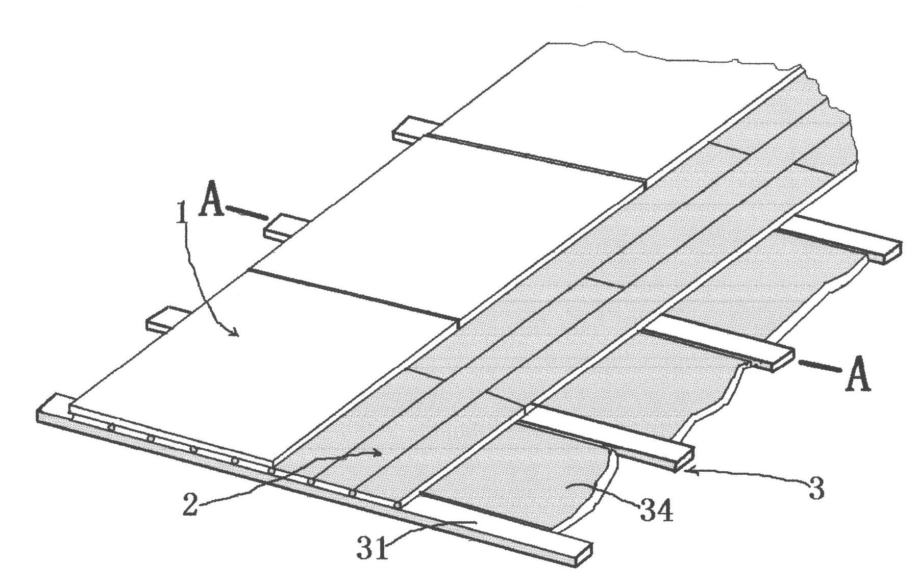
[0028] Such as figure 1 , 2, 3, 4, 5 and 6, the new heating system includes a decorative surface layer 1, a base plate 2, and a heat insulation layer 3. It is characterized in that the base plate 2 includes a base plate body 22 and a heat-conducting material. The thermally conductive medium layer 23 is provided with a first structure 221 on one side of the substrate body 22 and a second structure 222 on the other side. The first structure 221 on one substrate body 22 and the second structure on another substrate body 22 adjacent The two structures 222 can surround each other, and when the first structure 221 and the second structure 222 are surrounded, a longitudinally extending accommodation cavity 223 can be formed. The heat-conducting medium layer 23 is made of a heat-conducting material and is composited on the substrate body 22 On the front side, the heat conduction medium layer 23 includes a heat conduction portion 230 located on the front surface of the substrate body ...

Embodiment 2

[0032] Such as Figure 7 , 8 As shown in and 9, in this embodiment, the side of the heat conducting part 230 facing the substrate body 22 has a longitudinally extending concave convex body 234, and the substrate body 22 is provided with a longitudinally extending groove body for placing the above-mentioned concave convex body 234. 224. The concave convex body 234 is located on the center line of the heat conducting part 230 , and another heating body 4 is installed in the concave convex body 234 . The rest are similar to those in Example 1, and will not be described in detail.


PUM


Abstract

The invention relates to a novel heating system which comprises a decorative surface layer, substrates and matted thermal insulating layers, wherein the decorative surface layer can be made of ceramic tiles, stones, wooden floors, plastic floors, carpets and other ground decorative materials suitable for ground paving; each substrate is formed by compounding a substrate body and a heat-conducting medium layer, a longitudinally-extended heating element containing cavity can be encircled between two adjacent substrates, the wall of the cavity is the heat-conducting medium layer, and a heating element can be contained in the cavity; each matted thermal insulating layer is paved below each substrate to play roles of thermal insulation and fixation; after the substrates and the matted thermal insulating layers are partially or integrally paved, the decorative surface layer is paved on the surface through appropriate adhesives; and the heat of the heating element in each containing cavity is quickly transferred onto the upper surface of each substrate through each heat-conducting medium layer, and then, the heat is transferred to the decorative surface layer to realize the purpose of heating.

Description

technical field [0001] The invention belongs to the technical field of decoration and decoration materials, and relates to indoor heating technology, in particular to a low-temperature indoor ground heating technology. Background technique [0002] In the prior art, the heat-conducting medium or heating element of the geothermal floor is set separately from the floor. The most representative one is called "dry paving method". A new type of floor heating method in which floor heating pipes or heating cables are laid in the floor heating module. The dry floor heating module includes a heat-conducting medium layer and a heat-insulating layer. The heat-conducting medium layer is laid on the top of the heat-insulating layer. Floor heating coil grooves or heating cable grooves are provided, and the floor heating coil grooves or heating cable grooves are inverted Ω-shaped pipe grooves, and then the floor heating floor is suspended on the heat-conducting medium layer. This installat...

Claims


Application Information

Patent Timeline
Patent Type & Authority Applications(China)
IPC IPC(8): E04F15/02
Inventor 李渊
Owner 李渊
Learn More