
Air valve lift device and vehicle with same

A valve lift and valve technology, applied in valve devices, non-mechanically actuated valves, engine components, etc., can solve the problems of long transmission path, high application cost, and many parts, etc., and achieve short transmission path and manufacturing cost. Low, simple structure effect

Inactive Publication Date: 2020-01-03
深圳臻宇新能源动力科技有限公司
View PDF6 Cites 0 Cited by
  • Summary
  • Abstract
  • Description
  • Claims
  • Application Information

AI Technical Summary

Problems solved by technology

[0003] In related technologies, the main valve lift devices of the variable valve mechanism device type on the market are relatively complicated (need to design and arrange eccentric cams, etc., and the transmission path is long, and there are many parts), resulting in high application costs

Method used


Image

  • Air valve lift device and vehicle with same
  • Air valve lift device and vehicle with same

Examples


Embodiment Construction

[0028] Embodiments of the present invention are described in detail below, examples of which are shown in the drawings, wherein the same or similar reference numerals designate the same or similar elements or elements having the same or similar functions throughout. The embodiments described below by referring to the figures are exemplary only for explaining the present invention and should not be construed as limiting the present invention.

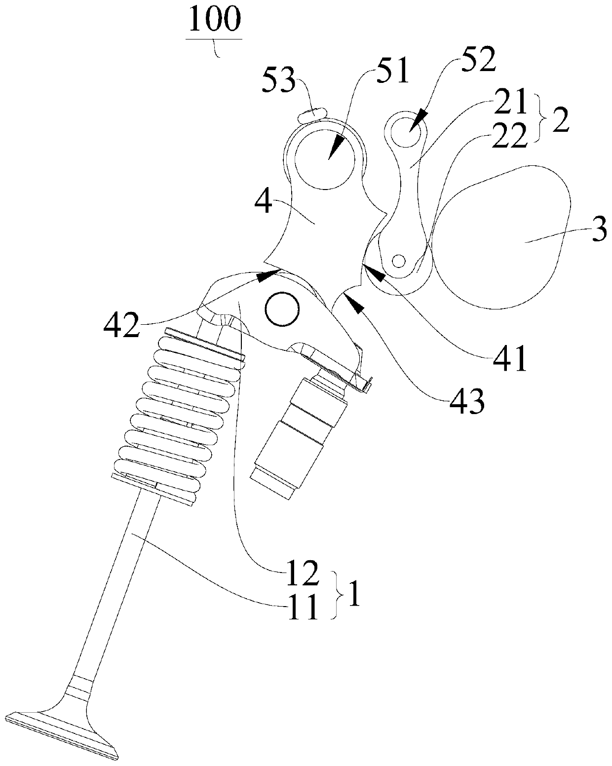
[0029] Refer below Figure 1-Figure 2 A valve lift device 100 according to an embodiment of the present invention and a vehicle having the same are described.

[0030] The valve lift device 100 according to the present invention includes: a valve assembly 1 , an intermediate rocker arm assembly 2 , a camshaft 3 , a driving rocker arm 4 and an actuating mechanism.

[0031] Among them, the valve assembly 1 includes the valve 11, the middle rocker arm assembly 2 includes the middle swing arm, the camshaft 3 rotates so that the shape of the...


PUM


Abstract

The invention discloses an air valve lift device and a vehicle with the same. The air valve lift device comprises an air valve assembly, a middle rocker assembly, a camshaft, a driving rocker and an actuating mechanism. The middle rocker assembly comprises a middle swing arm. The driving rocker is provided with a first profile face and a second profile face. The first profile face is matched withthe middle swing arm. The camshaft drives the driving rocker to act through the middle swing arm. The second profile face is matched with the air valve assembly so as to drive an air valve of the airvalve assembly to move. The actuating mechanism is used for driving the driving rocker to act round an adjusting axis so as to change the lift quantity of the air valve assembly. According to the airvalve lift device, the middle swing arm, the driving rocker and the actuating mechanism are arranged, and thus the lift of the air valve can be changed. In addition, the structure is simple, manufacturing cost is low, the power transmitting path from the camshaft to the air valve lift device is short, and thus driving force transmitting efficiency of the air valve lift device is high.

Description

technical field [0001] The invention belongs to the technical field of vehicle manufacturing, and in particular relates to a valve lift device and a vehicle with the same. Background technique [0002] For an engine with a fixed valve lift, a fixed cam profile and valve lift mechanism can be compromised according to the layout and performance requirements to ensure the performance and fuel consumption goals. However, according to the principle of internal combustion engines, in the low-to-medium speed and load range, a small valve lift can properly reduce the pumping loss, increase the charging efficiency, and improve the power and economy of the engine; The lift can ensure sufficient air intake, reduce throttling loss, and improve the high-speed performance of the engine. Through the variable valve lift technology, it can take into account the power and economy of medium and low speeds and high speeds. [0003] In the related art, the main valve lift devices of the variab...

Claims


Application Information

Patent Timeline
Patent Type & Authority Applications(China)
IPC IPC(8): F01L1/18F01L13/00F01L9/04F01L9/22
CPCF01L1/18F01L1/181F01L13/00F01L9/20
Inventor 李晓君
Owner 深圳臻宇新能源动力科技有限公司
Learn More