Cam-actuated engine hydraulic valve control

A control device and engine technology, applied in the direction of engine components, machines/engines, valve devices, etc., can solve the problems of valve seat ring impact, inability to change valve lift and opening duration, etc., to achieve flexible change, simple structure, The effect of improving power and economy

Inactive Publication Date: 2017-12-12
JILIN UNIV
View PDF7 Cites 0 Cited by
  • Summary
  • Abstract
  • Description
  • Claims
  • Application Information

AI Technical Summary

Problems solved by technology

[0003] The technical problem to be solved by the present invention is to overcome the shortcomings of the valve mechanism in the prior art that cannot change the valve lift and opening duration, and solve the impact problem on the valve seat when the valve is seated; provide a cam-driven engine Hydraulic valve control device

Method used


Image

  • Cam-actuated engine hydraulic valve control
  • Cam-actuated engine hydraulic valve control
  • Cam-actuated engine hydraulic valve control

Examples


Embodiment Construction

[0039] The present invention is described in detail below in conjunction with accompanying drawing:

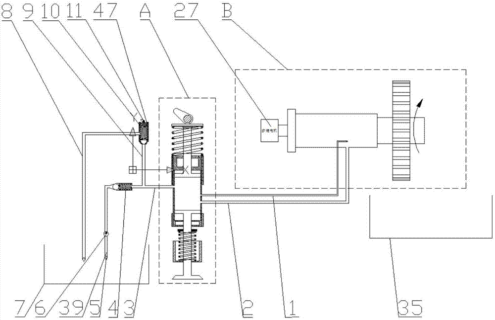
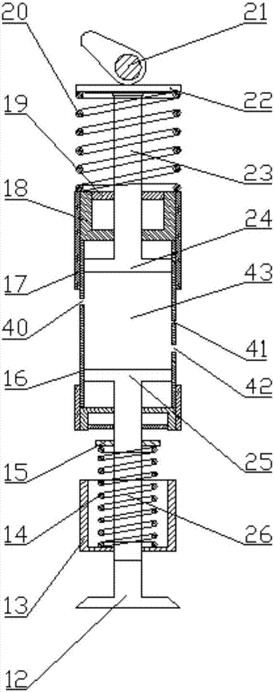
[0040] refer to figure 1 , the present invention consists of a hydraulic piston valve group A, a valve opening duration control mechanism, a valve seating buffer mechanism B, a valve lift control mechanism (including a one-way valve II10, a cam I11), an oil pipe I1, an oil pipe II2, an oil pipe III3, a one-way Valve Ⅰ4, filter 5, oil pump 6, oil tank Ⅰ7, oil pipe Ⅳ8, oil pipe Ⅴ9, oil tank Ⅱ35;

[0041] Oil tank Ⅰ7 and oil tank Ⅱ35 are common oil tanks for storing hydraulic oil.

[0042] The filter 5 is installed between the oil tank I7 and the oil pump 6, and its function is to filter the hydraulic oil sucked into the oil pump 6 to ensure the cleanliness of the hydraulic oil in the entire supply system.

[0043] The main function of the check valve Ⅰ4 is to separate the high pressure system from the low pressure system, which can not only supply oil to the high pressure syst...


PUM


Abstract

The invention belongs to the technical field of engines, particularly relates to a cam-driving engine hydraulic valve control device, overcomes the defect that a valve mechanism is unchangeable in valve lift and opening duration in the prior art and solves the problem of impact on a valve seat ring caused when a valve is seated. The cam-driving engine hydraulic valve control device comprises a hydraulic piston valve set, a valve opening duration control mechanism, a valve seating buffering mechanism, a valve lift control mechanism, a one-way valve I, an oil pump and an oil tank I, the valve lift control mechanism comprises a one-way valve II and a cam I, the oil tank I is communicated with the one-way I and the one-way II respectively, the oil pump is arranged between the one-way I and the oil tank I, the hydraulic piston valve set is communicated with the one-way valve I and the one-way valve II respectively, and the hydraulic piston valve set and the valve opening duration control mechanism are communicated with the valve seating buffering mechanism through an oil pipe I and an oil pipe II. The cam-driving engine hydraulic valve control device is simple in structure and flexibly changeable in valve lift and opening duration.

Description

technical field [0001] The invention belongs to the technical field of engines, and in particular relates to a cam-driven engine hydraulic valve control device. Background technique [0002] In the valve train of a traditional engine, the opening of the valve is driven by a cam, so the lift of the valve and the duration of the opening of the valve are not variable. However, in the actual work of the engine, a larger valve lift and opening duration are required at high loads, and the valve lift and opening time must be reduced at low loads; so the design of the valve train should adopt a The compromise of various comprehensive requirements for valve work requirements under different working conditions. Therefore, in order to meet the needs of different working conditions and the application of other advanced energy-saving technologies, improve the economy and power of internal combustion engines, and reduce harmful emissions, it is necessary to adopt variable valve lift and ...

Claims


Application Information

Patent Timeline
Patent Type & Authority Patents(China)
IPC IPC(8): F01L1/34
CPCF01L1/34
Inventor 解方喜洪伟苏岩代志尧李小平姜北平赵玉祥代春雨杨文海杨海洋姚卓彤
Owner JILIN UNIV
Why Eureka
Try Eureka