
Slurry transportation pipeline system for high viscosity coating device

A piping system, high-viscosity technology, applied in coatings, devices for coating liquids on surfaces, etc., can solve the problems of inconsistent film uniformity, streaks during the coating process, and poor V-shaped streaks, etc. Save electricity and eliminate the effect of coating streaks

Inactive Publication Date: 2012-04-25
SICHUAN COC DISPLAY DEVICES
View PDF4 Cites 2 Cited by
  • Summary
  • Abstract
  • Description
  • Claims
  • Application Information

AI Technical Summary

Problems solved by technology

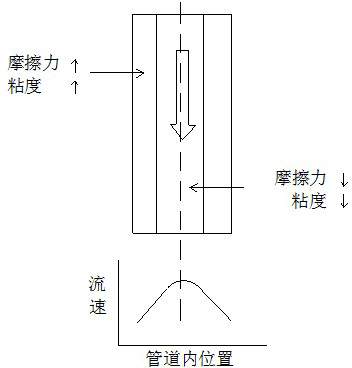
However, the coating process also has some shortcomings. Due to the characteristics of the high-viscosity electronic slurry, it will have a certain degree of "retention" near the inner wall of the pipeline during the process of passing through the slurry transportation pipeline of the coating equipment, resulting in There are differences in the state of slurry at different positions inside the transportation pipeline, as shown in the attached figure figure 1 shown
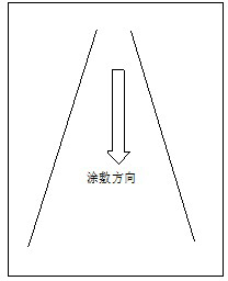
This situation is most obvious when the coating equipment is restarted after being suspended for a period of time. Inconsistencies in the uniformity of the slurry in the pipeline will cause the coated film to appear as shown in the attached picture figure 2 Defective chevron stripes shown
In addition, if there are differences in viscosity, thixotropy and other properties between different batches of high-viscosity electronic paste, it will also lead to streaks during the coating process after switching between different batches of paste
Coating streaks are one of the main defects in the coating process, and also the bottleneck for improving the coating quality

Method used


Image

  • Slurry transportation pipeline system for high viscosity coating device
  • Slurry transportation pipeline system for high viscosity coating device
  • Slurry transportation pipeline system for high viscosity coating device

Examples


Embodiment 1

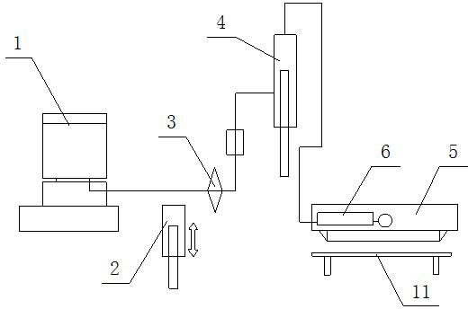
[0028] Such as Figures 3 to 6 As shown, a slurry transport pipeline system for high-viscosity coating equipment includes a supply tank 1, a booster pump 2, a filter 3, a syringe pump 4 connected in sequence, and a coating machine nozzle 5. A static agitator 6 is also connected before the machine nozzle 5, and the syringe pump 4 is connected with the static agitator 6. The static stirrer 6 includes a tubular shell 7 and a stationary spiral stirring member 8 arranged in the shell 7, and the spiral stirring member 8 forms a spiral channel in the shell 7 for generating a spiral motion of the high-viscosity fluid inside. As a preferred manner, as shown in this embodiment, the helical stirring member 8 and the shell 7 are detachably assembled. Both the shell 7 and the spiral stirring member 8 are smooth parts made of stainless steel. As shown in the figure, the spiral stirring member 8 is composed of 6 stationary spiral stirring units, and each spiral stirring unit is connected e...


PUM


Abstract

The invention which discloses a slurry transportation pipeline system for a high viscosity coating device belongs to the technical field of electronic slurry coating application. The system which comprises a coating machine nozzle is characterized in that: the front part of the coating machine nozzle is connected with a stationary stirrer which comprises a tubular housing and a stationary spiral stirring member arranged in the housing; and the spiral stirring member forms a spiral channel for making a high viscosity fluid in the housing generate a spiral motion. The slurry transportation pipeline system for the high viscosity coating device allows the uniformity of the slurry in the coating pipeline to be improved and the adverseness of coating strips caused by the uniformity difference before the slurry enters the nozzle to be avoided, so the coating film quality is improved.

Description

technical field [0001] The invention belongs to the technical field of electronic slurry coating application. Background technique [0002] The production of high-viscosity electronic paste film (such as the medium and barrier film of plasma display) is generally carried out in two ways: [0003] 1. Screen printing method, that is, the high-viscosity electronic paste is printed on the substrate through a printing plate through a printing machine. [0004] 2. Coating method, that is, the high-viscosity electronic slurry is coated on the substrate through the slurry transportation pipeline system through the coating equipment. [0005] At present, due to factors such as production efficiency and stability, the coating method is more widely used, especially for large-area, high-thickness (above 50 microns) high-viscosity electronic paste film layers, the coating method is the only commonly used method . However, the coating process also has some shortcomings. Due to the char...

Claims


Application Information

Patent Timeline
Patent Type & Authority Applications(China)
IPC IPC(8): B05C11/10
Inventor 段冰李玖沛王鹏年
Owner SICHUAN COC DISPLAY DEVICES
Learn More