Power converter
A power conversion device and converter technology, which are applied in the output power conversion device, the conversion of AC power input into AC power output, the conversion of irreversible AC power input into DC power output, etc., can solve the problem of DC link voltage increase, Resistor short circuit and other problems, to achieve the effect of reducing circuit scale, avoiding power consumption, and reducing manufacturing cost
- Summary
- Abstract
- Description
- Claims
- Application Information
AI Technical Summary
Problems solved by technology
Method used
Image

Examples
no. 1 approach
[0101]
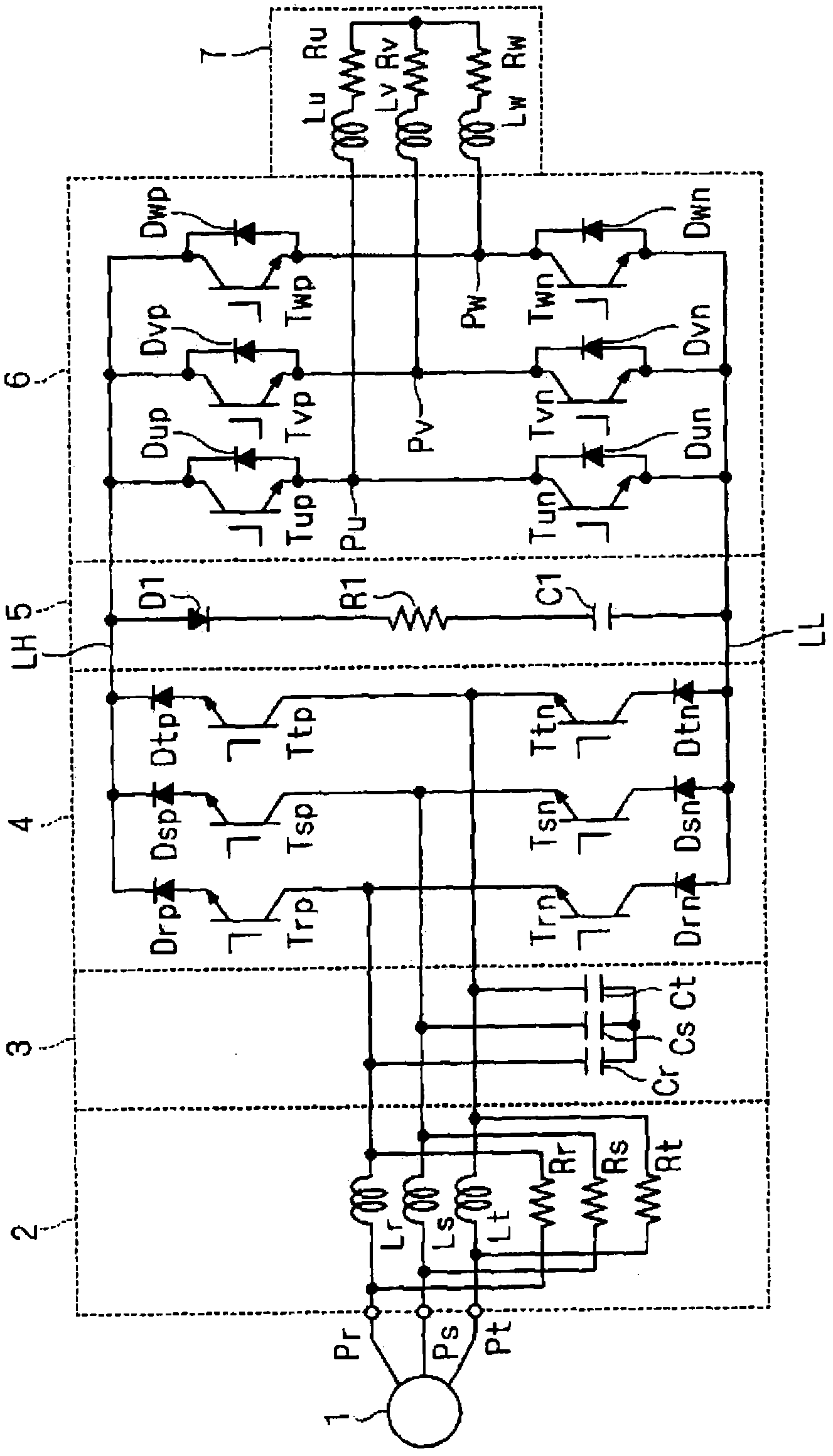
[0102] Such as figure 1 As shown, the direct AC power conversion device includes a current source converter 4 , a clamp circuit 5 , and a voltage source inverter 6 . The current-source converter 4, the clamp circuit 5, and the voltage-source inverter 6 are connected to each other in this order.
[0103] A three-phase AC phase voltage is input from a power source 1 to the direct AC power conversion device via three input terminals Pr, Ps, Pt, a reactor bank 2 , and a capacitor bank 3 . The direct AC power conversion device outputs AC voltage to the inductive load 7 through three output terminals Pu, Pv, Pw. The direct AC power conversion device further includes DC power lines LH, LL serving as DC links. Due to the function of the converter 4, the potential of the DC power supply line LH is higher than that of the DC power supply line LL.
[0104] Converter 4 includes, for example, six switching elements Trp, Tsp, Ttp, Trn, Tsn, Ttn. For convenience of description...
no. 2 approach
[0171] In the second embodiment, the object is to suppress the inrush current flowing to the capacitor C1 when the direct AC power conversion device is started. In addition, in normal operation after start-up, the current flow to the capacitor is suppressed by using a small resistance.
[0172] exist Figure 14 In the illustrated direct type power conversion device, with figure 1 Compared with the structure of the present invention, a current-limiting resistor group 8 is also provided on the input side of the converter 4 . The current limiting resistor group 8 is, for example, disposed between the input terminals Pr, Ps, Pt and the reactor group 2, and includes resistors R81, R82 and switches S81, S82. The resistors R81, R82 are provided, for example, between the input terminals Pr, Pt and the converter 4 (more specifically, for example, the reactor group 2). The resistance values of the resistors R81 and R82 are larger than the resistance value of the resistor R1, and th...
no. 3 approach
[0187] In the third embodiment, the configuration of the clamp circuit is different from that in the first embodiment. Figure 16 The conceptual configuration of the direct AC power conversion device according to the third embodiment is shown. In addition to the clamp circuit 5, the direct-type AC power conversion device is connected with Figure 14 same. Clamp circuit 5 with Figure 14 Compared with the clamping circuit 5, it also includes a switch S1. In addition, the current limiting resistor set 8 is not an essential requirement.
[0188] The switch S1 is connected in parallel with the resistor R1. Figure 16 In the example of , the switch S1 is an IGBT, its collector is placed on the DC power line LH side, and its emitter is placed on the DC power line LL side.
[0189] The switch S1 is controlled to be on / off by the control unit 9, for example. In addition, the control unit 9 outputs switching signals to the converter 4 and the inverter 6 according to the control d...
PUM
 Abstract
Description
Claims
Application Information
 - R&D
- Intellectual Property
- Life Sciences
- Materials
- Tech Scout
- Unparalleled Data Quality
- Higher Quality Content
- 60% Fewer Hallucinations
Browse by: Latest US Patents, China's latest patents, Technical Efficacy Thesaurus, Application Domain, Technology Topic, Popular Technical Reports.
© 2025 PatSnap. All rights reserved.Legal|Privacy policy|Modern Slavery Act Transparency Statement|Sitemap|About US| Contact US: help@patsnap.com