
Radiometric measuring device for measuring a filling level or a density of a filling material

A technology for measuring device and radiation quantity, which is applied in the direction of measuring device, radiation intensity measurement, lubrication indicator device, etc. It can solve the problems of poorly connected optical receivers and limited areas, and achieve the effect of high position resolution

Active Publication Date: 2012-04-18
EHNDRESS KHAUZER GMBKH KO KG
View PDF6 Cites 10 Cited by
  • Summary
  • Abstract
  • Description
  • Claims
  • Application Information

AI Technical Summary

Problems solved by technology

[0007] However, solid scintillation rods have the following disadvantage: Due to their size, they cannot be connected at all or only very poorly to currently available light receivers of very small construction, because in this case most of the light will be lost in the unused In the case of radiation passing through the photoreceiver
Therefore, the area that can be recorded metrologically with scintillation fiber bundles is limited

Method used


Image

  • Radiometric measuring device for measuring a filling level or a density of a filling material
  • Radiometric measuring device for measuring a filling level or a density of a filling material
  • Radiometric measuring device for measuring a filling level or a density of a filling material

Examples


Embodiment Construction

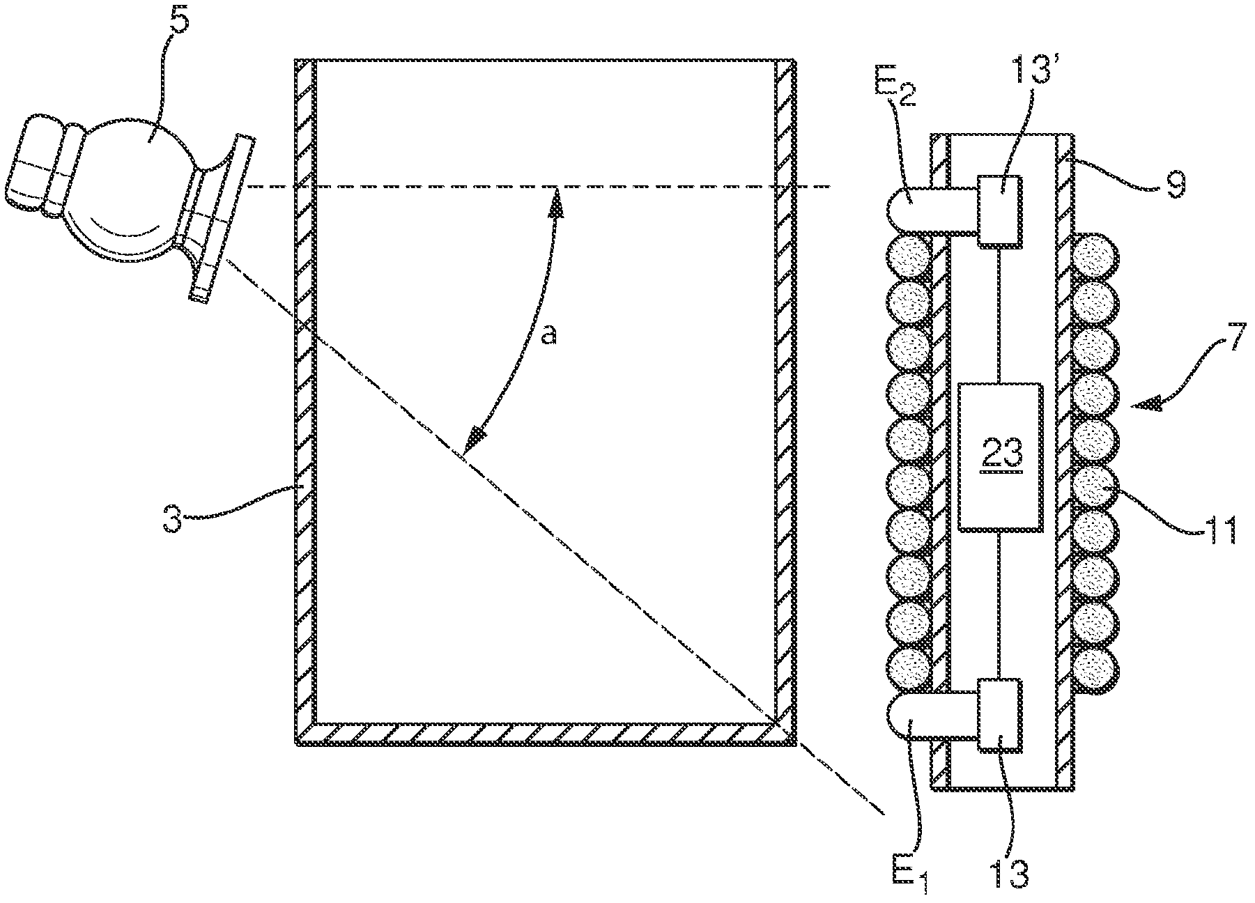
[0057] figure 1 Shows a schematic diagram of the principle of a measuring arrangement with a radiation dose measuring device according to the invention for measuring a physical measured variable, in particular level or density, of a filling substance in a container, and / or for monitoring the physical Whether the measured variable exceeds or falls below predetermined limit values.

[0058] The measurement arrangement comprises a container 3 which may be filled with a filling material 1 , and a radioactive radiator 5 mounted outside the container 3 which emits radioactive radiation penetrating the container 3 during the measurement operation. The radiation body 5 includes a radiation-proof container in which radioactive preparations, such as Co 60 or Cs 137 preparations, are inserted. The radiation-resistant container comprises a window through which radiation escapes and illuminates the container 3 in a radiation direction predetermined by the orientation of the window. A rad...


PUM


Abstract

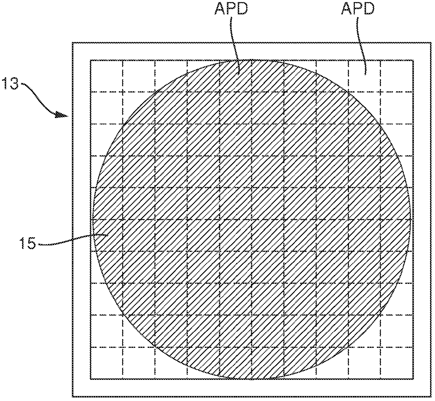
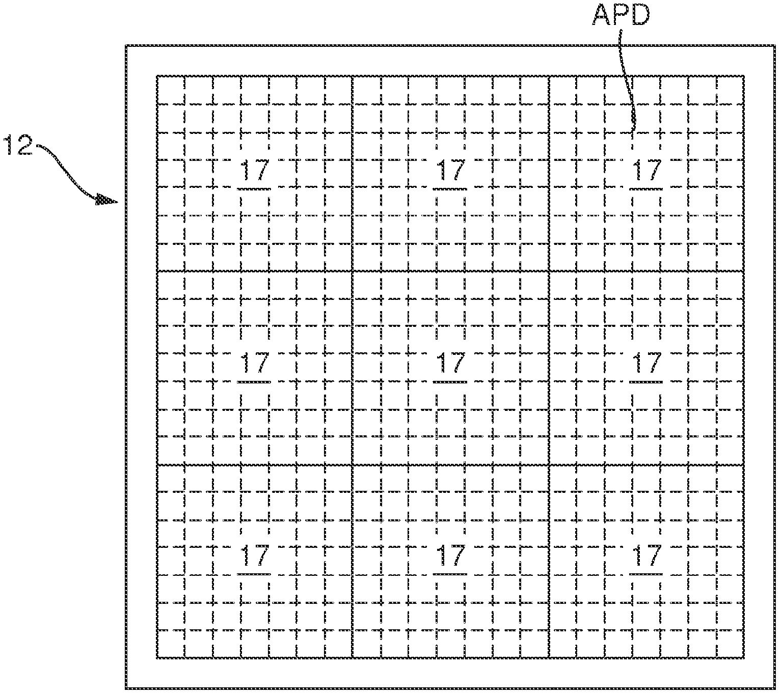
The invention relates to a radiometric measuring device for measuring a physical measurement variable, in particular a filling level or a density, of a filling material (1) in a container (3) and / or for monitoring whether the physical measurement variable exceeds or falls below a preset limiting value by way of a radioactive emitter (5) which, during operation, sends radioactive radiation throughthe container (3), and by way of a detector (7) which is arranged at a side of the container (3) opposite to the emitter (5) and which is used for detecting a radiation intensity which depends on thephysical measurement variable and penetrates the container (3) and for converting said radiation intensity into an electrical output signal, by means of said measuring device a very accurate measurement of the radiation intensity can be performed in a region that is located within the measurement range of the detector (7) and that can be defined in a very flexible manner. To this end, a detector (7) is provided which has a support (9, 37) onto which at least one scintillation fiber (11) is coiled which converts impinging radiometric radiation into light flashes, the light of which spreads toward the ends (E1, E2) of the respective scintillation fiber (11), the support comprising at least one array (13, 13') of avalanche photo diodes (APD) which are operated according to the Geiger mode and which convert impinging light into an electrical signal, at least one end (E1, E2) of each scintillation fiber (11) being connected to avalanche photo diodes (APD) of an array (13, 13'), the supportfurther comprising measuring device electronics that are connected to the avalanche photo diodes (APD) and generate the electrical output signal on the basis of the electrical signals provided by theavalanche photo diodes (APD).

Description

technical field [0001] The invention relates to a radiation measuring device for measuring a physical measurement variable of a filling substance in a container, in particular level or density, or for monitoring whether the physical measurement variable exceeds or falls short (or falls below) a predetermined limit value. To this end, the radioactive measuring device comprises a radioactive radiator, which emits radioactive radiation through the container during operation; The intensity is converted to an electrical output signal. Background technique [0002] Radiation measuring devices are generally always used when conventional measuring devices cannot be used due to particularly bad conditions at the measuring location. For example, extremely high temperatures and pressures or chemically and / or mechanically extremely harsh environmental influences often exist at the measurement location, which precludes the use of other measurement methods. [0003] In dosimetry techno...

Claims


Application Information

Patent Timeline
Patent Type & Authority Applications(China)
IPC IPC(8): G01F23/288G01N23/08G01T1/20
CPCG01F23/2885G01F23/288
Inventor 哈特穆特·达姆西蒙·魏登布鲁赫罗伯特·朔伊布勒
Owner EHNDRESS KHAUZER GMBKH KO KG
Learn More