Charging and discharging circuit for electrical system

A charging and discharging circuit and electrical system technology, applied in the mechanical and electrical field, can solve the problems of limited installation space, unfavorable heat dissipation of the current limiting circuit, unfavorable external power supply for field operations, etc., and achieve the effect of strong mobility and improved charging and discharging efficiency

Active Publication Date: 2012-04-11
ZOOMLION HEAVY IND CO LTD
View PDF5 Cites 5 Cited by
  • Summary
  • Abstract
  • Description
  • Claims
  • Application Information

AI Technical Summary

Problems solved by technology

However, the former needs an external power supply, which is not conducive to field work; the installation space of the latter is limited by the size of the driver, which makes it impossible to install a large power dissipation device and is not conducive to the heat dissipation of the current limiting circuit

Method used


Image

  • Charging and discharging circuit for electrical system
  • Charging and discharging circuit for electrical system
  • Charging and discharging circuit for electrical system

Examples


Embodiment Construction

[0015] The main realization principles, specific implementation modes and corresponding beneficial effects of the technical solutions of the embodiments of the present invention will be described in detail below in conjunction with each accompanying drawing.

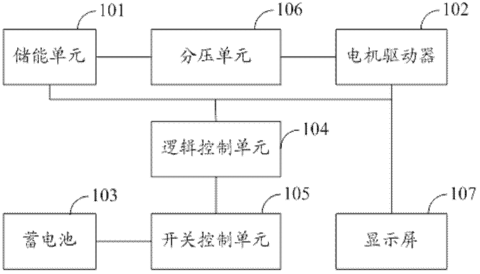
[0016] In order to solve the problems existing in the prior art, an embodiment of the present invention provides a charging and discharging circuit of an electrical system, such as figure 1 As shown, it includes: an energy storage unit 101, a motor driver 102, a storage battery 103, and also includes:

[0017] A logic control unit 104 is connected to the energy storage unit 101 and the motor driver 102 through a data bus;

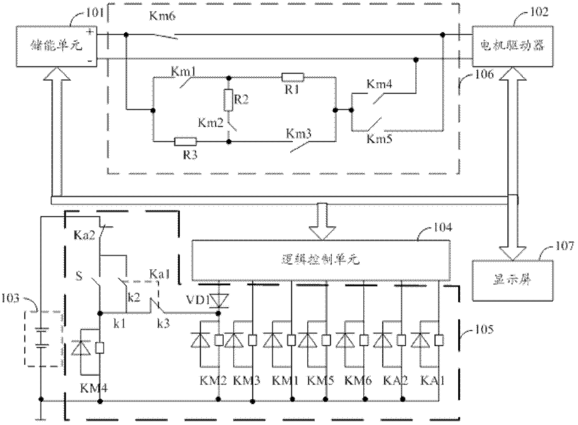
[0018] The switch control unit 105 is connected with the logic control unit 104 and the storage battery 103, receives the logic control signal sent by the logic control unit 104, and controls the opening and closing of each touch point located in the voltage dividing unit 106;

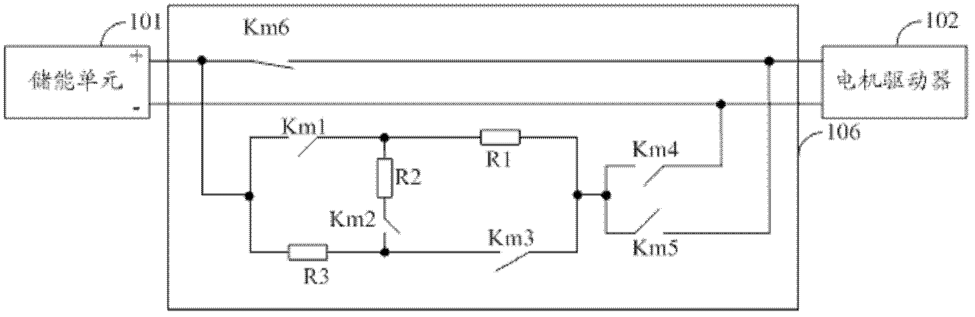
[0019] The voltage di...


PUM


Abstract

The invention relates to a technology in the mechanical and electrical field, in particular to a charging and discharging circuit for an electrical system. The charging and discharging circuit comprises an energy storing unit, a motor driver and a storage battery, and is characterized by further comprising a logical control unit, a switch control unit and a voltage-dividing unit, wherein the logical control unit is connected with the energy storing unit and the motor driver through data buses; the switch control unit is connected with the logical control unit and the storage battery, and is used for receiving a logical control signal transmitted by the logical control unit and controlling the switch-on and switch-off of each touch control point in the voltage-dividing unit; and the voltage-dividing unit is connected with the energy storing unit and the motor driver, and is used for receiving a switch control signal transmitted by the switch control unit, switching on or off each touch control point and adjusting the resistance of a voltage-dividing resistor. Due to the adoption of the charging and discharging circuit for the electrical system provided by the embodiment of the invention, the resistance value of the voltage-dividing resistor can be adjusted appropriately, the charging and discharging efficiencies are greatly increased, and high maneuverability is achieved.

Description

technical field [0001] The invention relates to the technical field of machinery and electricity, in particular to a charging and discharging circuit of an electrical system. Background technique [0002] The auxiliary electric power system of the hybrid electric machinery includes: electric energy storage unit, electric motor / generator and its driver, and system control unit. When designing and selecting, in order to improve the efficiency of energy use, a high-voltage drive system is often used, so it is necessary to select a high-voltage energy storage device and electrical accessories that match the high-voltage drive system. Usually, during equipment repair or maintenance, it is necessary to discharge the electric energy of the high-voltage energy storage device through an external load, so that the voltage drops to a safe voltage. Because mechanical equipment often works in various remote areas after leaving the factory, and the discharge energy release device is larg...

Claims


Application Information

Patent Timeline
Patent Type & Authority Applications(China)
IPC IPC(8): H02J7/00
CPCH02J7/00H02P7/20H02M3/00H02J7/0063H02J7/007182
Inventor 陈华东荣张迁
Owner ZOOMLION HEAVY IND CO LTD
Why Eureka
Try Eureka