Self-locking wire end earthing clamp

A technology of grounding clips and wire ends, applied in the direction of conductive connection, connection, electrical component connection, etc., can solve the problems of difficult operation, loss of protection, low efficiency, etc., and achieve the effect of simple operation

Inactive Publication Date: 2012-04-11
ELECTRIC POWER RES INST OF GUANGXI POWER GRID CO LTD
View PDF5 Cites 12 Cited by
  • Summary
  • Abstract
  • Description
  • Claims
  • Application Information

AI Technical Summary

Problems solved by technology

However, for the 500kV line, the first three types of clip structures are not reasonable, and they are easy to fall off, making the working point lose protection
Although the spiral type can ensure reliable grounding, using it is labor-intensive, inefficient, and difficult to operate, and it is easy to cause construction personnel to sometimes not operate according to safety regulations, and there are certain safety risks

Method used


Image

  • Self-locking wire end earthing clamp
  • Self-locking wire end earthing clamp
  • Self-locking wire end earthing clamp

Examples


Embodiment Construction

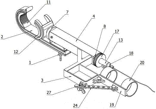
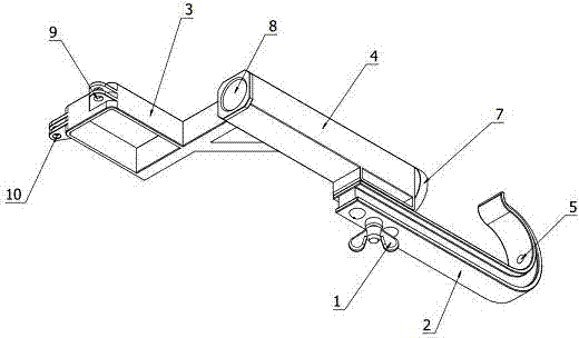
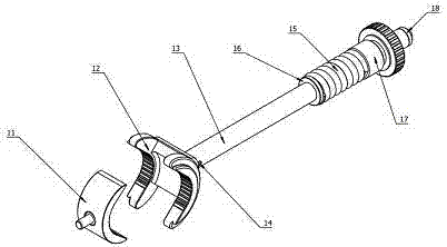
[0017] Such as Figure 1 to Figure 7 As shown, the self-locking wire end grounding clamp of the present invention includes a clamp main body, a secondary clamp and an angle adjustment mechanism. One end of the clamp main body is the main wire chuck 2, the other end is a bracket 3, and the middle is connected by a clamp body 4. The bottom of the main line chuck 2 is provided with a ground wire connector 1, the main line chuck 2 and the clamp body 4 are fixedly connected by rivets, the clamp body 4 is a tubular structure with two ends open, and the clamp body 4 is fixedly installed with a guide tube near the end of the main line chuck 2 7. The other end of the clip body 4 is fixed with a threaded pipe 8, the bracket 3 is fixed on the side of the clip body 4, and the bracket 3 is provided with a first hinge joint 9 and a second hinge joint 10; the auxiliary line clamp includes a fixed half clamp The head 11 and the movable half chuck 12, the fixed half chuck 11 is inserted into t...


PUM


Abstract

The discloses a self-locking wire end earthing clamp which comprises a wire holder main body, a sub wire clamp and an angle adjusting mechanism, the earthing clamp provided by the invention utilizes a resetting self-lock principle to realize the purpose of clamping high-pressure wire, a clamp head is splayed and closed through only drawing back and relaxing a bracing wire, thereby thereby quicklycompleting the clamping of the high-pressure wire and loosen action, and operation is very simple; in addition, the earthing clamp is provided with the angle adjusting mechanism, the angle adjusting mechanism is utilized to regulate an angle between the wire clamp and an operation rod according to the requirements, thereby adapting to relative position variation of an operator and the tested high-pressure wire.

Description

technical field [0001] The invention relates to a high-voltage wire detection tool, in particular to a self-locking wire end grounding clip. Background technique [0002] The grounding clamp at the wire end is a safety device used to temporarily short-circuit and ground the power-off transmission wire. Its function is to prevent the harm to the human body caused by the sudden incoming power or the induced voltage generated by the adjacent high-voltage live equipment during the maintenance of the high-voltage transmission wire. At present, the clamps used by various power grid companies mainly include double tongue type, flat type, impact type and spiral type. However, for the 500kV line, the first three types of clip structures are not reasonable, and they are easy to fall off, making the working point lose protection. Although the spiral type can ensure reliable grounding, the use of it is labor-intensive, inefficient, and difficult to operate, and it is easy to cause cons...

Claims


Application Information

Patent Timeline
Patent Type & Authority Applications(China)
IPC IPC(8): H01R11/14H01R4/28
Inventor 陈渊许飞王凯郑广平汪丽川周柯宾凯
Owner ELECTRIC POWER RES INST OF GUANGXI POWER GRID CO LTD
Why Eureka
Try Eureka