
Steel belt wheel type continuous casting machine with casting blank conveying mechanism for continuous casting lead belt

A technology of conveying mechanism and continuous casting machine, which is applied in the field of steel belt wheel continuous casting machine for continuous casting of lead strips, which can solve the problems of unguaranteed production, easy deformation, and great influence of self-weight, etc., so as to avoid casting billet hanging in the air and deformation Even fracture, enhance the effect of supporting capacity

Inactive Publication Date: 2012-04-11
SICHUAN HUASHEN NEW ENERGY EQUIP
View PDF7 Cites 4 Cited by
  • Summary
  • Abstract
  • Description
  • Claims
  • Application Information

AI Technical Summary

Problems solved by technology

When using the above casting slab conveying mechanism, the slab between the casting mouth and the conveying roller table moves upwards, and part of it is suspended in the air, which is greatly affected by its own weight.
The traditional steel-belt wheel-type continuous casting machine is mainly used to prepare aluminum rods and copper rods for wire rod production. The cross-section of the billet is small and the strength of aluminum and copper is high. It will deform under the action of its own weight; however, the lead density is extremely high and the quality is soft, so the casting slab between the casting port and the conveying roller table is easily deformed or even broken under the action of its own weight, which cannot guarantee smooth production, especially for large sections. lead belt

Method used


Image

  • Steel belt wheel type continuous casting machine with casting blank conveying mechanism for continuous casting lead belt
  • Steel belt wheel type continuous casting machine with casting blank conveying mechanism for continuous casting lead belt

Examples


Embodiment Construction

[0018] The present invention will be further described below in conjunction with the accompanying drawings and embodiments.

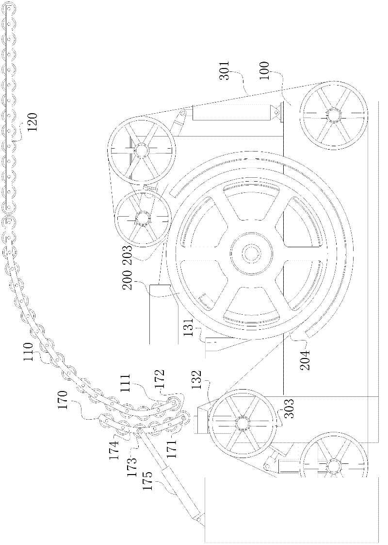
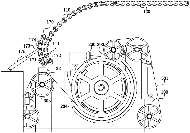
[0019] The steel-belt wheel-type continuous casting machine for continuous casting lead belt provided with a slab conveying mechanism of the present invention comprises a frame 100, a crystallization wheel 200, a steel belt wheel system, a headless steel belt 301, and a slab conveying mechanism; The outer cylindrical surface of the crystallization wheel 200 is provided with a concave crystallization cavity; the steel belt 301 is tightened by the steel belt wheel system and bypasses the crystallization wheel 200, and the part of the crystallization cavity of the crystallization wheel 200 is closed by the steel belt 301 to form a mold cavity One end of the cavity is the casting port 203, and the other end is the casting port 204; the billet conveying mechanism includes an approach bridge 110 and a conveying roller table 120, and one end of the approach bri...


PUM


Abstract

The invention relates to a continuous casting equipment for a nonferrous alloy, providing a steel belt wheel type continuous casting machine with a casting blank conveying mechanism for a continuous casting lead belt. A longitudinal plane which passes through the axial direction of a crystallizing wheel is used for dividing the crystallizing wheel into a first zone and a second zone; a pouring gate is positioned on the upper part of the first zone; a throwing hole is positioned on the lower part of the second zone; a casting blank support mechanism which is fixed on a rack and is aslant downwards extended from the outer side of the second zone to be above the throwing hole is arranged; the higher end of an approach bridge is positioned above the crystallizing wheel; the lower end of the approach bridge is positioned above one end of the casting blank support mechanism, which is far away from the crystallizing wheel; one end of a conveying roller bed is positioned above the crystallizing wheel and is connected with one higher end of the approach bridge; and the other end of the conveying roller bed is positioned on the outer side of the first zone of the crystallizing wheel. The phenomenon that the lead belt between the throwing hole and the conveying roller bed deforms even is broken under the action of dead load can be avoided by adding the casting blank support mechanism, lowering the gradient of the approach bridge and providing support for the throwing hole and the approach bridge. The steel belt wheel type continuous casting machine is suitable for producing lead belts, especially lead belts with large cross sections.

Description

technical field [0001] The invention relates to continuous casting equipment for non-ferrous alloys, in particular to a steel belt wheel continuous casting machine for continuous casting of lead strips provided with a slab conveying mechanism. Background technique [0002] The electrode grid acts as an electronic current collector and at the same time plays the role of immobilizing active substances, and is an important part of the lead-acid battery. During the use of lead-acid batteries, porous active substances will permeate sulfuric acid, causing corrosion of the grid, affecting the cycle life of the grid, and further affecting the durability of the battery; at the same time, the transfer of electrons requires the grid to have Good electrical conductivity requires that the corrosion products of the grid have low impedance during use, especially the positive grid. There is a close relationship between the corrosion resistance of the grid and the crystal structure, so in o...

Claims


Application Information

Patent Timeline
IPC IPC(8): B22D11/06
Inventor 冯旭龙唐晓东
Owner SICHUAN HUASHEN NEW ENERGY EQUIP
Learn More