
Ventilation structure for slip ring cover of wound-rotor motor

A technology of wire wound motor and slip ring cover, which is applied in the direction of cooling/ventilation devices, electrical components, electromechanical devices, etc. It can solve the problems of unsmooth discharge of toner, affect the operation of the motor, and affect the cooling of slip rings, etc., so as to eliminate hidden dangers in use , Reduce the accumulation of toner and save costs

Inactive Publication Date: 2012-04-04
SEC ELECTRIC MACHINERY
View PDF2 Cites 5 Cited by
  • Summary
  • Abstract
  • Description
  • Claims
  • Application Information

AI Technical Summary

Problems solved by technology

When this type of motor is designed, it is often because the motor manufacturer follows the idea of ​​axial ventilation, which leads to unsmooth discharge of toner and blockage of toner, which leads to slip ring failure.
[0003] At present, in order to improve the cooling effect of the slip ring, some manufacturers adopt the practice of adding a cooling fan to the slip ring cover. The cooling fan blows air to the slip ring. The slip ring cover is made into an octahedron, and two cooling fans are installed on both sides of the octahedron. The wind generated by the fan blows directly to the slip ring to improve the cooling of the slip ring. This kind of forced cooling structure not only has a high cost, but also once the power supply of the fan fails, it will inevitably affect the cooling of the slip ring, thus affecting the entire motor. run

Method used


Image

  • Ventilation structure for slip ring cover of wound-rotor motor
  • Ventilation structure for slip ring cover of wound-rotor motor

Examples


Embodiment Construction

[0011] The specific implementation manner of the present invention will be described below in conjunction with the accompanying drawings.

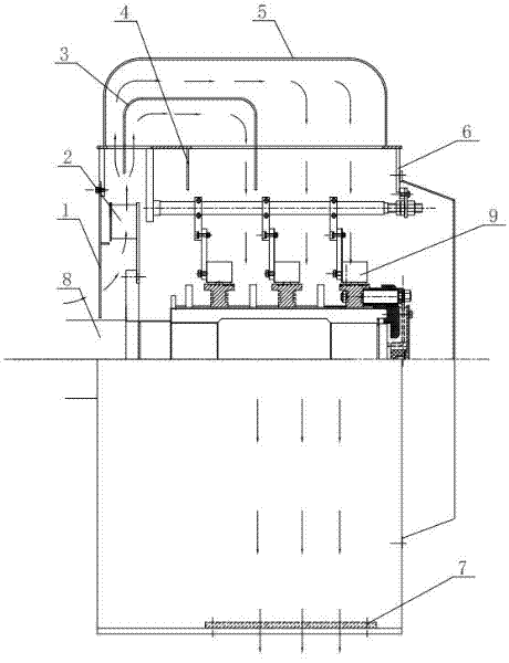
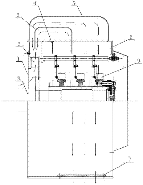
[0012] Such as figure 1 As shown, the present invention is provided with fan blades 2 inside the front side air inlet of the casing 6, the fan blades 2 are driven by the motor shaft 8, and the outer wind deflector 5 is arranged on the upper part of the casing 6, and passes through the lower part of the outer wind deflector 5. Bending inner deflectors 3 and straight inner deflectors 4 construct a number of air passages, and the outlets of the air passages are respectively located at the upper part of each set of slip rings 9 and windings; and bending inner deflectors 3 and straight inner deflectors 4 The end is designed with a smaller air collection port. An air outlet is provided at the bottom of the casing 6 . The air inlet is equipped with an air inlet net plate 1, and the air outlet is equipped with an air outlet net plate 7 and an ai...


PUM


Abstract

The invention discloses a ventilation structure for a slip ring cover of a wound-rotor motor. A fan blade is arranged at the inner side of a front side air inlet of a cover shell and is driven by a motor shaft; an outer air guide plate is arranged at the upper part of the cover shell, a plurality of air channels are constructed at the lower part of the outer air guide plate through bent inner deflection plates and straight inner deflection plates, and outlets of the air channels are positioned at the upper parts of each group of slip rings and windings respectively; and an air outlet is arranged at the bottom of the cover shell. In the ventilation structure for the slip ring cover of the wound-rotor motor, as cooling air is guided to the upper part of the slip ring end cover and then directly blows to the slip rings through fluid design under the conditions of without increasing the manufacture cost and guaranteeing the safety and reliability of the motor, the cooling effect of the slip rings can be greatly improved, accumulation of carbon powders brought about by axial ventilation can be reduced to the greatest extent, and the reliability of a slip ring brush holder system is effectively improved, so that factories and enterprises with better environmental conditions can save cost when selecting motors with the protection grade IP23, and simultaneously the hidden troubles during use can be eliminated.

Description

technical field [0001] The invention relates to the technical field of motors, in particular to a slip ring cover ventilation structure of a wound motor. Background technique [0002] The slip ring problem of wound motors is a persistent headache that plagues the motor industry and industrial and mining enterprises. The main reason is not that the slip rings are not well ventilated, the toner discharge is not effective, local carbon deposits are short-circuited, and blasting directly affects the entire production line. Operation. Slip rings can be roughly divided into two categories according to their protection levels: the first category is the environment where the factory environment is harsh and there is a lot of dust such as powder and coal. Such environments usually use a slip ring ventilation structure with a higher protection level to isolate it from the outside world. There is an independent slip ring cooling air path to avoid slip ring failures caused by environme...

Claims


Application Information

Patent Timeline
IPC IPC(8): H02K9/28
Inventor 王坤
Owner SEC ELECTRIC MACHINERY
Learn More