Exhausting braking system

An exhaust braking and exhaust pipe technology, applied in engine control, machine/engine, output power, etc., can solve the problems of reducing exhaust braking efficiency, wasting exhaust braking time, etc., to shorten the time, The effect of strengthening air intake and improving efficiency

Active Publication Date: 2012-03-28
WEICHAI POWER CO LTD
View PDF6 Cites 2 Cited by
  • Summary
  • Abstract
  • Description
  • Claims
  • Application Information

AI Technical Summary

Problems solved by technology

[0003] However, during the research and practice of the prior art, the inventors of the present invention have found that in the existing implementations, there is no reuse of the excess high-pressure gas discharged from the exhaust pipe, which wastes the time of exhaust braking and reduces the Efficiency of the exhaust brake

Method used


Image

  • Exhausting braking system
  • Exhausting braking system
  • Exhausting braking system

Examples


Embodiment Construction

[0015] In order to enable those skilled in the art to better understand the solutions of the embodiments of the present invention, the embodiments of the present invention will be further described in detail below in conjunction with the drawings and implementations.

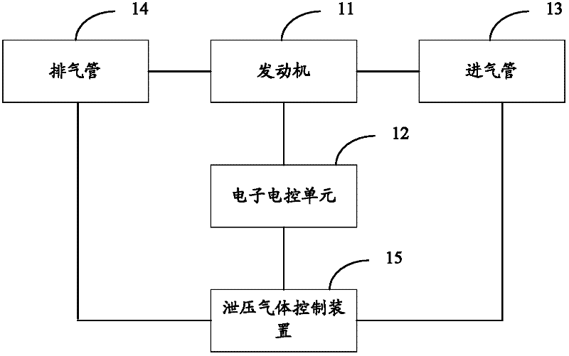
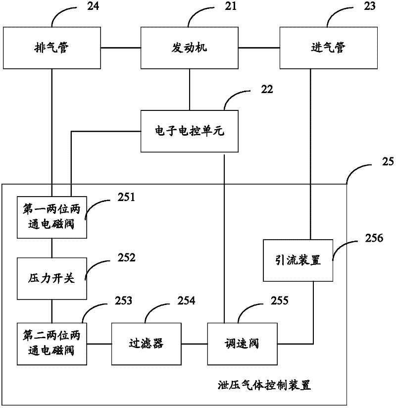
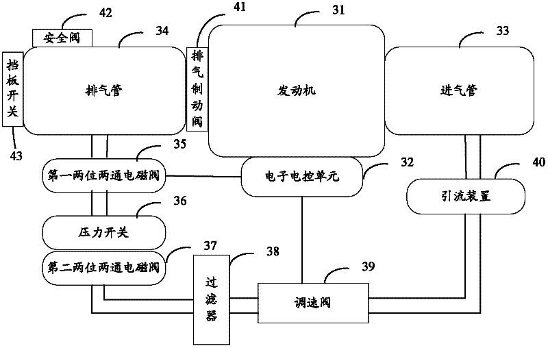
[0016] see figure 1 , is a structural schematic diagram of the first exhaust braking system provided by the present invention, said system comprising: an engine 11, an electronic control unit (ECU, Electronic Control Unit) 12, an intake pipe 13, an exhaust pipe 14 and a pressure relief A gas control device 15, wherein the engine 11 is respectively connected to the electronic control unit 12, the intake pipe 13 and the exhaust pipe 14, and the pressure relief gas control device 15 is connected to the electronic control unit 12, The intake pipe 13 and the exhaust pipe 14 are connected by pipes.

[0017] Preferably, in this embodiment, the engine can be connected to the exhaust pipe through an exhaust brake butter...


PUM


Abstract

The invention provides an exhausting braking system, which comprises an engine, an electronic electric unit, air inlet pipe and an air outlet pipe, wherein the engine is respectively connected with the electronic electric unit, the air inlet pipe and the air outlet pipe; the system further comprises a pressure released gas control device which is respectively connected with the electronic electric unit, the air inlet pipe and the exhaustion pipe by pipes. In the exhausting braking system provided by the invention, excessive gas at high pressure from the exhaustion pipe are recycled by the pressure released gas control device, which means that the excessive compressed air produced in exhausting and braking and to be discharged can be returned to the air inlet pipe by a serial of control elements; the air inlet of the air inlet pipe is improved; the exhausting braking efficiency is improved; and the time for exhausting braking is reduced.

Description

technical field [0001] The invention relates to the technical field of automobile electronics, in particular to an exhaust braking system. Background technique [0002] With the development of automotive electronic technology, there are more and more developments and applications of engines and exhaust brakes. Among them, the exhaust brake is the method of closing the engine exhaust passage, so that the engine piston is subjected to the back pressure of the gas during the exhaust stroke, preventing the engine from running and producing a braking effect, thereby achieving the purpose of controlling the vehicle speed. When the pressure in the exhaust manifold reaches a certain value, a part of the high-pressure gas is discharged from the exhaust pipe to release the pressure, so as to ensure that the pressure in the exhaust manifold will not continue to rise. At this time, the engine essentially becomes an air compressor to consume the energy of the car, that is, to convert th...

Claims


Application Information

Patent Timeline
Patent Type & Authority Applications(China)
IPC IPC(8): F02D13/04
Inventor 靳海龙雷保军乔海周
Owner WEICHAI POWER CO LTD
Why Eureka
Try Eureka