
Asynchronous successive approximation analog-to-digital converter and conversion method

An asynchronous successive approximation, analog-to-digital converter technology, applied in the direction of analog-to-digital conversion, code conversion, instruments, etc., can solve the problems of high power consumption efficiency discount, limit the overall accuracy of analog-to-digital converter, increase chip power consumption, etc. Achieve the effects of improving power consumption efficiency, reducing capacitance matching and peripheral circuit requirements, and low power consumption

Inactive Publication Date: 2012-03-21
BEIJING UNIV OF TECH
View PDF2 Cites 34 Cited by
  • Summary
  • Abstract
  • Description
  • Claims
  • Application Information

AI Technical Summary

Problems solved by technology

[0003] The traditional synchronous successive approximation analog-to-digital converter requires a high-speed system clock (sampling frequency times the number of converter resolution digits), whether it is generated internally or directly input from off-chip will increase the extra power consumption of the chip, so that the successive approximation The high power efficiency of the
[0004] Since the successive approximation ADC requires an array of capacitors in increments of two, the matching between the minimum and maximum capacitors limits the overall accuracy of the ADC
The use of unit capacitance and centrosymmetric layout can reduce the impact of this limitation, but it cannot fundamentally solve this problem. Many designs use digital correction to improve the accuracy of capacitance matching.

Method used


Image

  • Asynchronous successive approximation analog-to-digital converter and conversion method
  • Asynchronous successive approximation analog-to-digital converter and conversion method
  • Asynchronous successive approximation analog-to-digital converter and conversion method

Examples


Embodiment Construction

[0036] Specific embodiments of the present invention are described below in conjunction with the accompanying drawings:

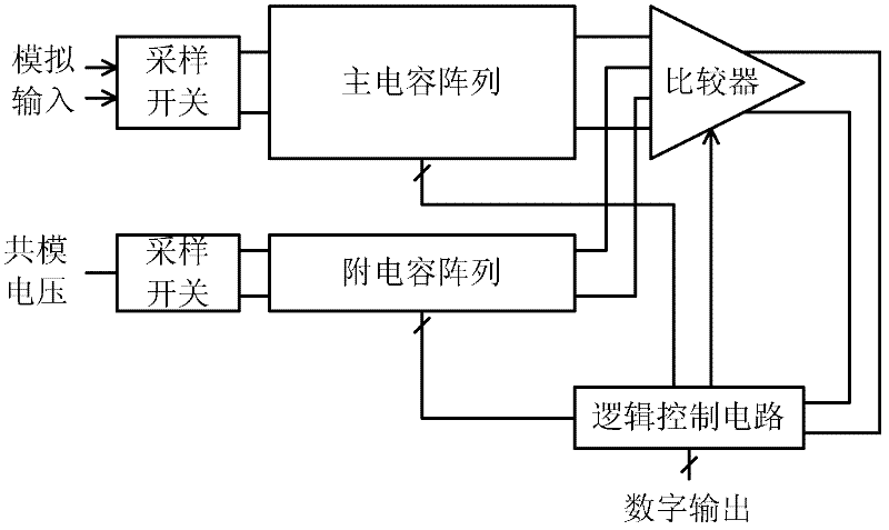
[0037] Such as figure 1 As shown, the structural block diagram of an asynchronous successive approximation analog-to-digital converter of the present invention includes: a sampling network, a main capacitor array, an auxiliary capacitor array, a comparator and a logic control circuit. What is realized in the embodiment of the present invention is an 8-bit successive approximation analog-to-digital converter with a sampling rate of 50 MHz.

[0038] Since the input signal of the main capacitor array is an analog signal that changes with time, a bootstrap sampling switch is used; the input signal of the auxiliary capacitor array is a common-mode reference voltage that does not change with time, so a CMOS sampling switch is used.

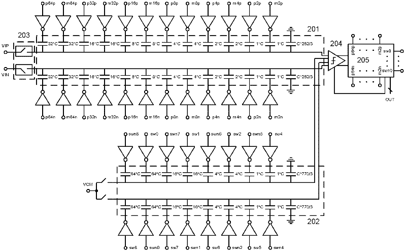
[0039] figure 2 The circuit diagrams of the main capacitor array and the auxiliary capacitor array are given. The main capacito...


PUM


Abstract

The invention discloses an asynchronous successive approximation analog-to-digital converter and a conversion method. The asynchronous successive approximation analog-to-digital converter comprises: a sampling network, a main capacitor array, an auxiliary capacitor array, a comparator and a logic control circuit. The sampling network of the main capacitor array uses a bootstrap switch. The sampling network of the auxiliary capacitor array uses a CMOS switch. Each two same capacitors in the main capacitor array are in a group. A capacitance value size is reduced as two times relationship. Top crowns of all the capacitors and the bootstrap switch are connected and output to the comparator. The each two same capacitors in the auxiliary capacitor array are in one group. The capacitance value size is reduced as four times relationship. The top crowns of all the capacitors and the CMOS switch are connected and output to the comparator. The comparator comprises a preamplifier and a latch and compares the size of an output voltage of the main capacitor array and the auxiliary capacitor array. The logic control circuit uses an asynchronous sequential control capacitor array to successively complete switching. A power consumption efficiency of the analog-to-digital converter can be effectively raised. And demands of capacitor coupling and a peripheral circuit can be reduced. The method is suitable for a deep-submicron low voltage design.

Description

technical field [0001] The present invention relates to an asynchronous successive approximation analog-to-digital converter and a conversion method, in particular to an asynchronous successive approximation converter which improves power consumption efficiency, reduces capacitance matching and peripheral circuit requirements by improving the retrieval method, and is suitable for deep submicron low power supply voltage. approximation to the analog-to-digital converter. technical background [0002] The successive approximation analog-to-digital converter is a type used in medium precision and medium sampling rate. Compared with other types of analog-to-digital converters such as flash type and pipeline type, it has the highest power consumption efficiency. It is widely used in medical and portable equipment. Applications. [0003] The traditional synchronous successive approximation analog-to-digital converter requires a high-speed system clock (sampling frequency times the...

Claims


Application Information

Patent Timeline
IPC IPC(8): H03M1/38
Inventor 黄冠中林平分
Owner BEIJING UNIV OF TECH
Learn More