Circuit for inhibiting interference signal and carrying out surge protection
A technology for surge protection and interference suppression, applied in emergency protection circuit devices, emergency protection circuit devices for limiting overcurrent/overvoltage, circuit devices, etc.
- Summary
- Abstract
- Description
- Claims
- Application Information
AI Technical Summary
Problems solved by technology
Method used
Image
Examples
Embodiment 1
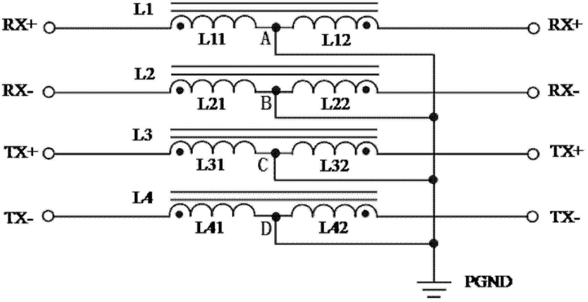
[0024] attached figure 1 Shown is a schematic diagram of the circuit structure of the Ethernet interference suppression and lightning protection circuit of the present invention. It can be seen from the figure that on the two pairs of differential lines RX+ and RX- and TX+ and TX- of Ethernet, four impedance elements L1, L2, L3 and L4 are connected in series respectively, among which: the first differential line RX+ is connected in series The impedance element L1 consists of two series reactor coils L11 and L12. The connection method of the reactor coils L11 and L12 is an anti-parallel connection, and the connection terminal A of the two reactor coils in series is also called the anti-parallel connection terminal A, and the lead wire is connected to the ground PGND. In the same way, impedance elements L2~L4 are connected in series on the differential lines RX-, TX+, and TX- in the same way, and each impedance element also includes coils L21 and L22, L31 and L32, L41 and ...
Embodiment 2
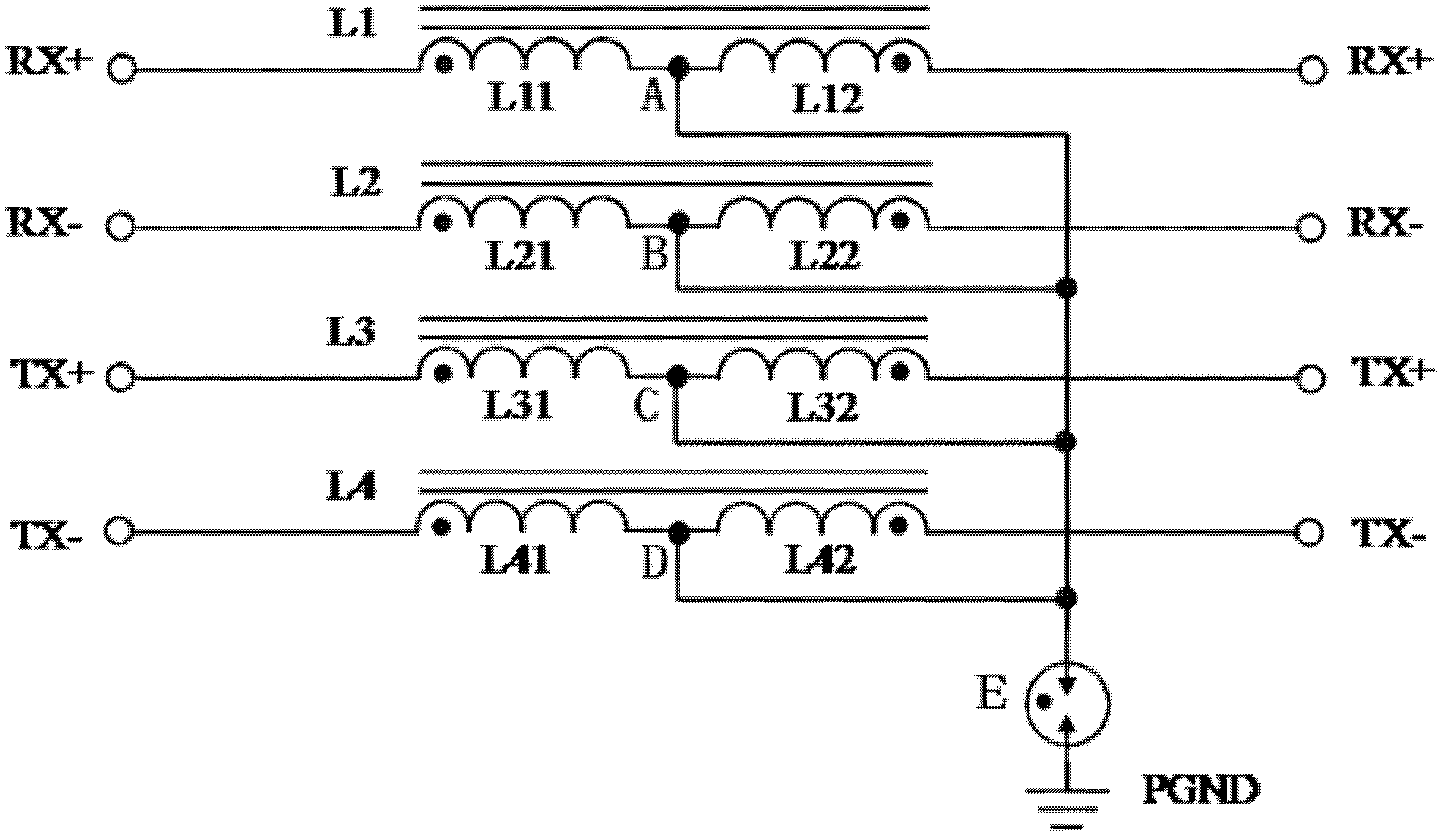
[0035] figure 2 shown in the figure 1 On the basis of , the schematic diagram of the circuit structure of each reactor coil is grounded through the voltage sensitive element. This circuit is mainly used in some special environments. Due to the high grounding resistance of the ground grid, there is a lot of interference and the voltage difference of the ground grid potential is large, so as to avoid unnecessary interference that may cause abnormal line transmission. In the figure, the anti-parallel connection terminals A, B, C, and D of the impedance elements L1, L2, L3, and L4 are connected to the ground wire through the voltage sensitive element E.
[0036] When the line voltage is lower than the working voltage of the voltage sensitive element E, the voltage sensitive element E is in an open circuit state, and each differential line is open with the impedance elements L1, L2, L3, L4 and the ground wire; when there is a surge current or voltage wave, When the voltage sens...
Embodiment 3
[0040] image 3 shown in the figure 1 On the basis of , a schematic diagram of the circuit structure of a three-terminal voltage sensitive element connected between the differential line and the series impedance element and grounded. From the figure, it can be seen that the figure 1 On the basis of , the discharge tubes F1, F2 are connected in parallel between the differential line and the series impedance and grounded to ensure that the reactor coils in the impedance elements L1, L2, L3, and L4 will not be burned by excessive surge current. Among them, the discharge tubes F1 and F2 are the same and are three-terminal gas discharge tubes.
[0041] In the mine zone LPZ0 A Zone (Every object in this zone may be directly struck by lightning and conduct all the lightning current, and the electromagnetic field strength in this zone is not attenuated.) and lightning protection zone LPZ0 B (The objects in this area cannot be directly struck by the lightning current correspondin...
PUM
 Abstract
Description
Claims
Application Information
 - R&D
- Intellectual Property
- Life Sciences
- Materials
- Tech Scout
- Unparalleled Data Quality
- Higher Quality Content
- 60% Fewer Hallucinations
Browse by: Latest US Patents, China's latest patents, Technical Efficacy Thesaurus, Application Domain, Technology Topic, Popular Technical Reports.
© 2025 PatSnap. All rights reserved.Legal|Privacy policy|Modern Slavery Act Transparency Statement|Sitemap|About US| Contact US: help@patsnap.com


