Independent cam engine brake device

An engine braking, cam-type technology, applied in the direction of engine control, engine components, machines/engines, etc., can solve the problems of high cost, high braking power, complex compression braking structure, etc., and achieve low cost, good rigidity, Avoid the effect of braking force drop and failure

Inactive Publication Date: 2012-03-21
CHINA FIRST AUTOMOBILE
View PDF5 Cites 6 Cited by
  • Summary
  • Abstract
  • Description
  • Claims
  • Application Information

AI Technical Summary

Problems solved by technology

At present, the engine braking applied on the engine is mainly divided into two types: vent braking and compression braking: vent braking is simple in...

Method used


Image

  • Independent cam engine brake device
  • Independent cam engine brake device
  • Independent cam engine brake device

Examples


Embodiment Construction

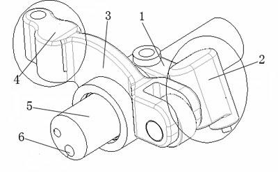
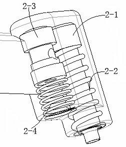
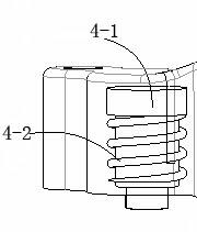
[0013] Below in conjunction with accompanying drawing, the present invention will be further described: as figure 1 , 2 , shown in 3, a kind of independent cam type engine brake device, by rocker shaft support 1, braking active part 2, exhaust rocker 3, brake driven part 4, rocker shaft 5, brake oil Road 6 and exhaust valve 7, characterized in that: there is a brake oil circuit 6 inside the rocker shaft 5, the rocker shaft support 1, and the exhaust rocker arm 3 are installed on the rocker shaft 5, and the rocker shaft support 1. There is an oil circuit inside the exhaust rocker arm 3 that communicates with the brake oil circuit 6. The end of the rocker arm shaft support 1 is the brake active part 2, and the front end of the exhaust rocker arm 3 is the brake slave part 4; the brake active The part 2 is a cavity structure, the cavity of the brake active part 2 communicates with the oil circuit of the rocker shaft support 1, the control valve 2-3 is installed in the cavity of t...


PUM


Abstract

The invention relates to an independent cam engine brake device, which is characterized in that: oil passages in a rockshaft stool and an exhaust rocker are communicated with a brake oil passage; the tail end of the rockshaft stool is a brake driving part; the front end of the exhaust rocker is a brake driven part; a cavity of the brake driving part is communicated with the oil passage of the rockshaft stool; a brake driving piston is arranged on the right of a control valve in the cavity of the brake driving part, and is sleeved with a driving piston return spring; a cavity of the brake driven part is communicated with the oil passage of the exhaust rocker; a brake driven piston is arranged in the cavity of the brake driven part, and is sleeved with a driven piston return spring; and an exhaust valve is arranged above the tail end of the brake driven part. The independent cam engine brake device is simple in structure, high in rigidity and low in cost, can effectively make up the defect of foot brake power, avoids brake force reduction and failure caused by using a brake for a long time, and ensures vehicle safety.

Description

technical field [0001] The invention relates to an independent cam type engine braking device, which is applied to a diesel engine, and is especially suitable for a vehicle with a large total mass, which cannot meet the braking requirements of the vehicle under high-speed and heavy-load conditions only by the main brake of the vehicle itself. Background technique [0002] The total mass of modern vehicles is getting bigger and bigger, and the speed is getting higher and higher. Only relying on the main braking system of the vehicle itself can no longer meet the braking requirements of the vehicle under high-speed and heavy-load conditions. In order to ensure the safety performance of the vehicle, an auxiliary braking device must be added. Engine braking is to use the mechanical loss, pumping loss and compression work of the engine to generate the braking function through the turning of the car to the engine, thereby increasing the braking power of the car. [0003] When goi...

Claims


Application Information

Patent Timeline
IPC IPC(8): F01L13/06F02D13/04
Inventor 王鹏程邓金金
Owner CHINA FIRST AUTOMOBILE
Why Eureka
Try Eureka