
Screw-type and piston-type combined double-stage compressor set and intermediate container

A technology of screw compressors and compressor units, which is applied in the direction of machines/engines, liquid displacement machinery, mechanical equipment, etc., can solve the problems of scattered auxiliary equipment, large footprint, and complicated operation, and achieve simplified equipment and equipment operation Reliable, volume-efficient results

Inactive Publication Date: 2014-04-02
大连冷星企业有限公司
View PDF6 Cites 0 Cited by
  • Summary
  • Abstract
  • Description
  • Claims
  • Application Information

AI Technical Summary

Problems solved by technology

[0003] The present invention aims to realize a two-stage compressor unit composed of a screw machine and a piston machine, and at the same time solve the technical problems that the auxiliary equipment between the two-stage compressors is relatively scattered, occupies a large area, has many connecting pipes, and is complicated to operate

Method used


Image

  • Screw-type and piston-type combined double-stage compressor set and intermediate container
  • Screw-type and piston-type combined double-stage compressor set and intermediate container
  • Screw-type and piston-type combined double-stage compressor set and intermediate container

Examples


Embodiment 1

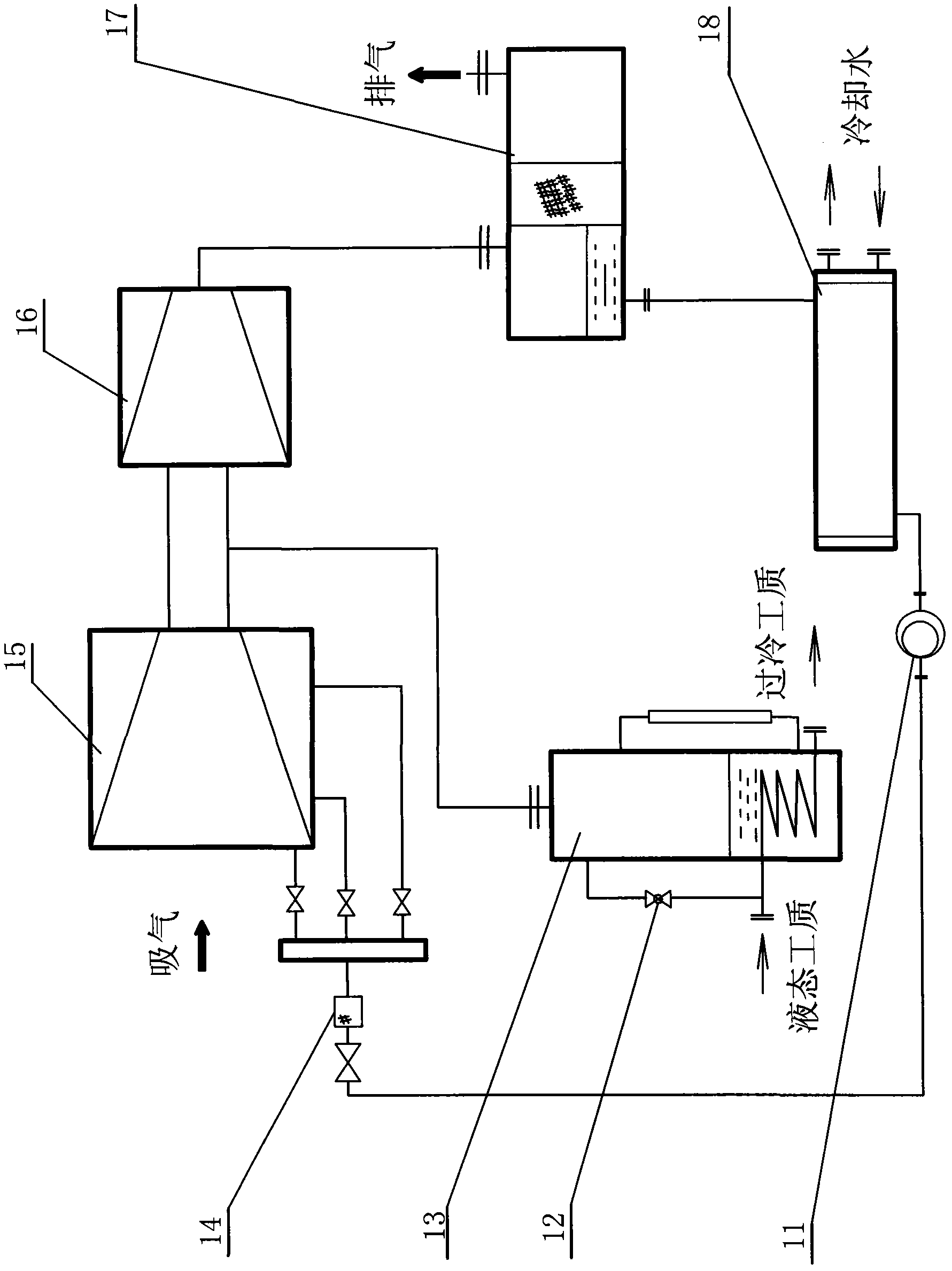
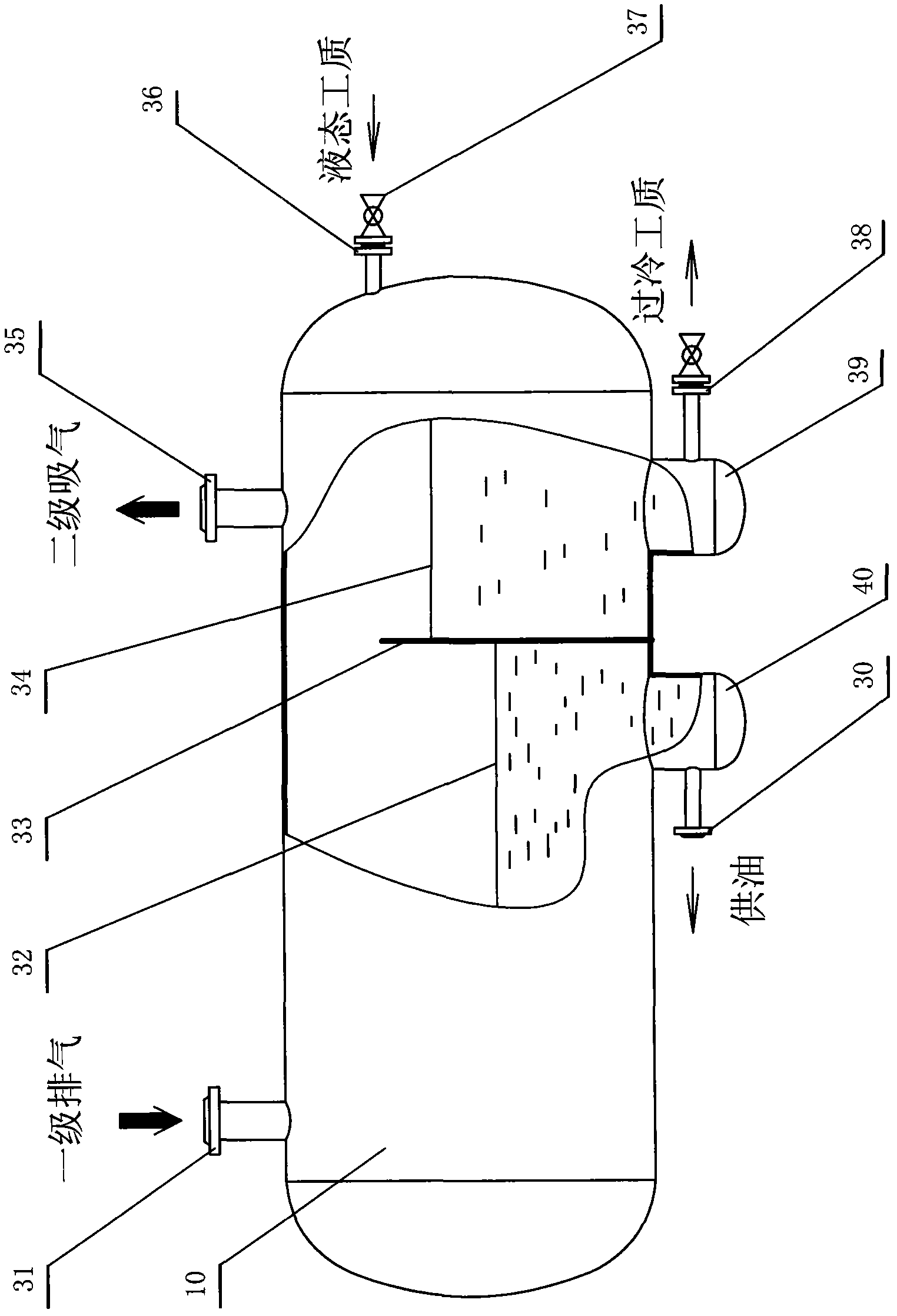
[0024] Embodiment 1, a kind of screw type that is provided with horizontal intermediate container and piston type mixing two-stage compressor unit and horizontal intermediate container (see image 3 , 5 ) is a two-stage compressor unit composed of a one-stage screw compressor 51, a two-stage piston compressor 55 and a horizontal intermediate container 10. A horizontal intermediate container is connected between the exhaust pipeline of the first-stage screw compressor and the suction pipeline of the second-stage piston compressor. The horizontal intermediate container 10 is a horizontal tank, and the inside of the tank is divided into a section (left section) of a cavity 32 for storing oil, and another section (right section) of a cavity 34 for storing liquid working fluid. And the partition plate 33 of setting. There is a gap on the upper part of the partition, which communicates with the cavity for storing oil and the cavity for storing liquid working fluid, and can also be...

Embodiment 2

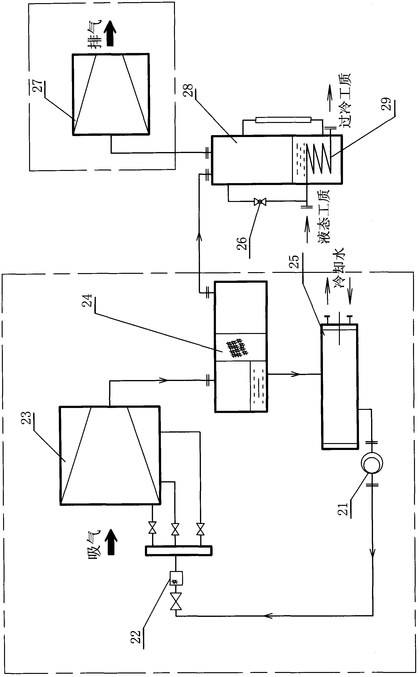
[0025] Embodiment 2, a kind of screw type that is used in refrigeration system and is provided with vertical intermediate container screw type and piston type mixed two-stage compressor unit and vertical intermediate container (see Figure 4 , 7 ) is a two-stage compressor unit composed of a one-stage screw compressor 71, a two-stage piston compressor 73 and a vertical intermediate container 72. There is a vertical intermediate container ( Figure 4 ). The vertical intermediate container is a vertical tank, and the tank is provided with a partition 47 that separates the inner cavity of the tank into one section (lower section) for oil storage, and the other section (upper section) for storage of liquid working fluid. There is a through pipe 44 in the middle of the partition, which is used as a channel to communicate with the cavity for storing oil and the cavity for storing liquid working fluid. The primary exhaust pipeline 42 communicates with the upper part of the oil sto...

Embodiment 3

[0026] Embodiment 3, a screw-type and piston-type mixed two-stage compressor unit used in a refrigeration system and provided with a horizontal intermediate container and a horizontal intermediate container with a heat exchange pipeline (see Image 6 and see image 3 ), a two-stage compressor unit consisting of a first-stage screw compressor 61, a second-stage piston compressor 65, and a horizontal intermediate container 10. A horizontal intermediate container is connected between the exhaust pipeline of the first-stage screw compressor and the suction pipeline of the second-stage piston compressor. The horizontal intermediate container is a horizontal tank, and there is a partition in the tank that divides the inner cavity of the tank into one section (left section) for oil storage, and the other section (right section) for storage of liquid working fluid ( 33), the gap on the upper part of the partition communicates with the cavity for storing oil and the cavity for storing...


PUM


Abstract

The invention relates to a screw-type and piston-type combined double-stage compressor set and an intermediate container. The screw-type and piston-type combined double-stage compressor set comprises a first-stage screw compressor and a second-stage piston compressor. A partition plate is arranged in the intermediate container to divide the intermediate container into a cavity body for storing oil and a cavity body for storing a liquid working medium; the cavity body for storing the oil and the cavity body for storing the liquid working medium are communicated; a first-stage exhaust pipeline is communicated with the cavity body for storing the oil; a first-stage oil supply pipeline is communicated with the cavity body for storing the oil under a liquid level; the cavity body for storing the liquid working medium is communicated with a second-stage air suction pipeline above the liquid level; an output throttling pipeline of a condenser is communicated with the cavity body for storing the liquid working medium, or an output pipeline connected in parallel with the output throttling pipeline penetrates the cavity body for storing the liquid working medium through a heat exchange pipeline to exchange heat under the liquid level; and the output pipeline extends out from the lower part of the cavity body for storing the liquid working medium. The intermediate container achieves the functions of oil separation, oil cooling and intermediate working medium cooling, and is used for artificial refrigeration occasions of minus 30 DEG C-minus 60 DEG C and the heat pump heat supply occasions of which the heat sources are lower than 0 DEG C, thereby, the working efficiency is greatly improved, the occupied spaces are few, adapter pipes are few, and the loss of refrigeration capacity is less.

Description

technical field [0001] The invention relates to a two-stage compressor unit of a refrigeration system composed of a primary compressor, a secondary compressor and auxiliary equipment, which are then combined with a condenser, an evaporator, etc. to form a refrigeration or heat pump system. At the same time, the invention also relates to the auxiliary equipment between the two stages of the two-stage compressor unit. A multi-functional intermediate container realizes functions such as an oil separator, an oil cooler, and an intercooler for the first-stage compression and exhaust. The invention is especially suitable for artificial refrigeration occasions at -30°C to -60°C and heat pump heating occasions where the heat source is below zero, such as in the fields of industry, engineering, biology, pharmacy, military, scientific research, food, chemical industry, etc., can be used Ammonia, Freon and other working fluids. Background technique [0002] In the 1960s, my country's ...

Claims


Application Information

Patent Timeline
Patent Type & Authority Patents(China)
IPC IPC(8): F04B39/00F04B41/06
Inventor 洪星
Owner 大连冷星企业有限公司
Learn More