Sweeping and brushing device for road sweeping vehicle
A technology of road sweeper and horizontal moving device, which is applied in the direction of road cleaning, construction, cleaning methods, etc. It can solve the problems that the roller brush is easy to be impacted, the effect of garbage cleaning is not good, and the working angle is easy to change. The effect of cleaning the area, protecting it from damage, and reducing the impact force
- Summary
- Abstract
- Description
- Claims
- Application Information
AI Technical Summary
Problems solved by technology
Method used
Image

Examples
Embodiment 1
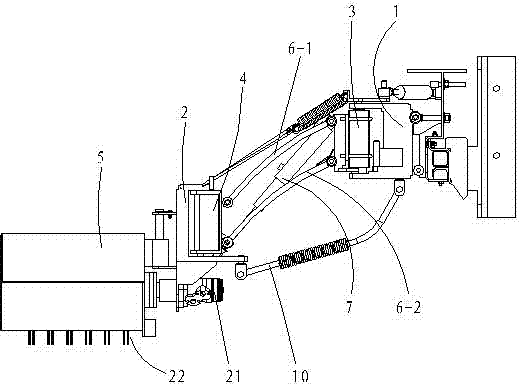
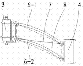
[0032] The sweeping device of the road sweeper of the present embodiment, such as figure 1 and figure 2 As shown, it includes an inner bracket 1 and an outer bracket 2 arranged at the front end of the road sweeper. The inner bracket 1 is provided with a first rotating shaft 3 , and the outer bracket 2 is provided with a second rotating shaft 4 and a brush sweeper 5 . The sweeper 5 is a rolling brush 22 connected with the output end of the second hydraulic motor 21 arranged on the outer support 2 .
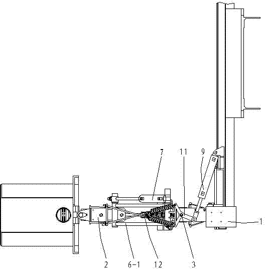
[0033] Such as image 3 and Figure 4 As shown, two upper connecting rods 6-1, two lower connecting rods 6-2 and lifting cylinder 7 are hinged between the first rotating shaft 3 and the second rotating shaft 4, the upper connecting rod 6-1, the lower connecting rod 6- 2. The first rotating shaft 3 and the second rotating shaft 4 form the first parallel four-bar mechanism 8 in the vertical plane, and the lifting cylinder 7 is located on the diagonal of the projection plane of th...
Embodiment 2
[0040] This embodiment is an improvement on the basis of Embodiment 1, as Figure 8 and Figure 9As shown, the difference is that it also includes a horizontal moving device 17 located at the front end of the road sweeper. The horizontal moving device 17 includes a guide rail 17-1 located at the front end of the road sweeper, the guide rail 17-1 is equipped with a chain 17-2, the chain 17-2 is connected with a sprocket 17-3, and the sprocket 17-3 is connected with the first hydraulic motor 18. The first hydraulic motor 18 is fixed on the inner support 1. The inner bracket 1 is placed on the guide rail 17-1.
[0041] The first parallel four-bar mechanism 8 is hinged to the lift cylinder 7 and a compensating spring 19 is connected thereto.
[0042] A return spring 20 is also provided on the crank 11 , and the other end of the return spring 20 is fixed on the inner bracket 1 .
[0043] The sweeper 5 is a disc brush 22 connected to the output end of the second hydraulic motor ...
Embodiment 3
[0045] This embodiment is an improvement on the basis of Embodiment 2, as Figure 10 As shown, the difference is that it also includes a horizontal moving device 17 located at the front end of the road sweeper. The horizontal moving device 17 includes a guide rail 17-1 located at the front end of the road sweeper, the guide rail 17-1 is equipped with a rack 17-2, the rack 17-2 is meshed with a gear 17-3, and the gear 17-3 is connected to the first hydraulic motor 18. The first hydraulic motor 18 is fixed on the inner support 1. The inner support 1 is placed on the guide rail 17-1.
PUM
 Abstract
Description
Claims
Application Information
 - Generate Ideas
- Intellectual Property
- Life Sciences
- Materials
- Tech Scout
- Unparalleled Data Quality
- Higher Quality Content
- 60% Fewer Hallucinations
Browse by: Latest US Patents, China's latest patents, Technical Efficacy Thesaurus, Application Domain, Technology Topic, Popular Technical Reports.
© 2025 PatSnap. All rights reserved.Legal|Privacy policy|Modern Slavery Act Transparency Statement|Sitemap|About US| Contact US: help@patsnap.com