
Electroplating apparatus and electroplating method thereof

A technology of electroplating device and electroplating tank, which is applied in the direction of electrolysis process, electrolysis components, cells, etc., can solve the problems of low current density, uneven current density, high current density, etc.

Active Publication Date: 2012-03-14
AVARY HLDG (SHENZHEN) CO LTD +1
View PDF4 Cites 7 Cited by
  • Summary
  • Abstract
  • Description
  • Claims
  • Application Information

AI Technical Summary

Problems solved by technology

However, there is a phenomenon of uneven current density when the current autonomous tool flows into the substrate to be plated, that is, the current density at the edge of the circuit board close to the clamp point of the fixture is relatively high, and the current density at the center of the circuit board far away from the clamp point of the fixture is relatively small

Method used


Image

  • Electroplating apparatus and electroplating method thereof
  • Electroplating apparatus and electroplating method thereof
  • Electroplating apparatus and electroplating method thereof

Examples


Embodiment Construction

[0041] The electroplating device and electroplating method provided by the technical solution will be described in detail below with reference to the accompanying drawings and multiple embodiments.

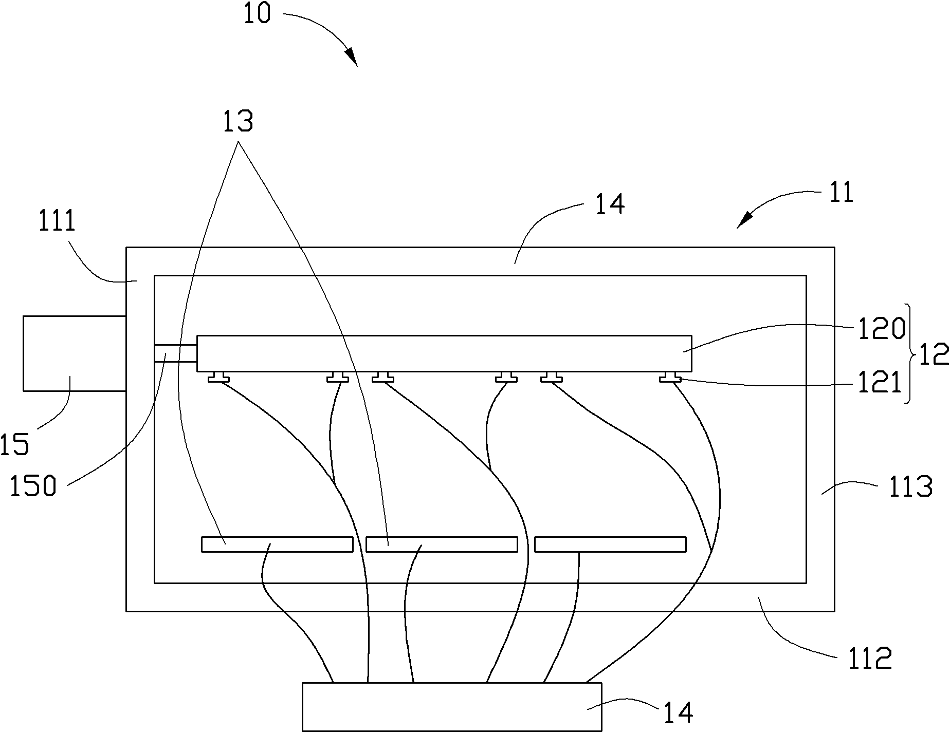
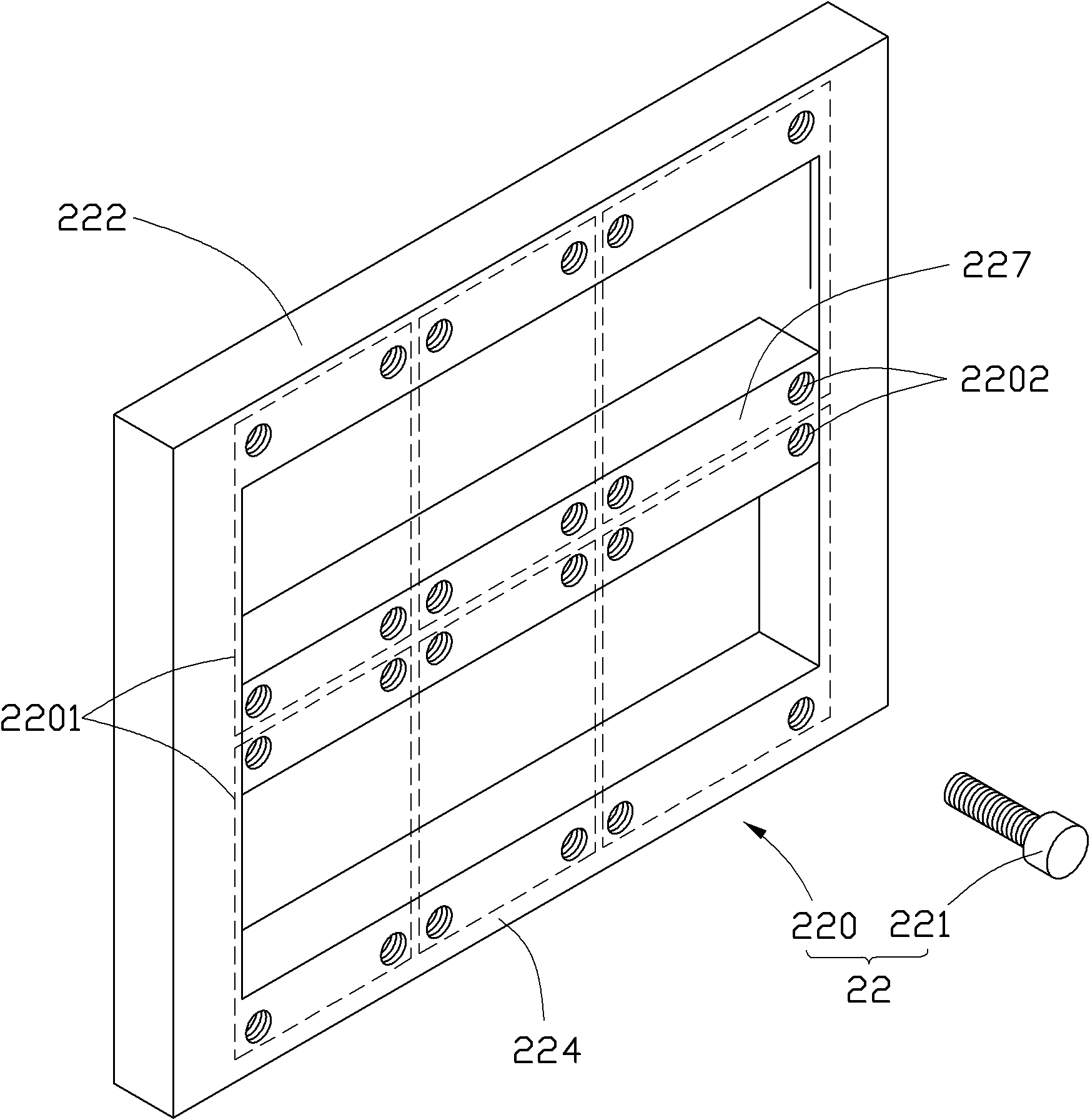
[0042] Please also refer to figure 1 and figure 2 , The first embodiment of the technical solution provides an electroplating device 10 for electroplating a plurality of regions to be plated that are electrically insulated from each other on a substrate. The electroplating device 10 includes an electroplating tank 11 , a cathode fixing structure 12 , a plurality of anodes 13 , a voltage controller 14 and a driver 15 .

[0043] The electroplating tank 11 can be a cuboid tank. The electroplating tank 11 includes a first side plate 111 , a second side plate 112 , a third side plate 113 and a fourth side plate 114 connected end to end, wherein the first side plate 111 is opposite to the third side plate 113 , the second side panel 112 is opposite to the fourth side panel 114 . Th...


PUM


Abstract

The invention relates to an electroplating apparatus, which is provided for electroplating a substrate comprising a plurality of areas requiring electroplating, wherein the areas requiring electroplating are electrically insulated. The electroplating apparatus comprises an electroplating bath, a cathode fixation structure, a plurality of anodes and a voltage controller. The cathode fixation structure comprises an installation frame and a plurality of electrical conductivity fixation components. The electrical conductivity fixation components are provided for installing the substrate on the installation frame, and conducting current to the substrate. Each electroplating-required area of the substrate is provided with at least an electrical conductivity fixation component. Each anode is corresponding to an electroplating-required area of the substrate arranged on the installation frame. The voltage controller forms electrical connections with a plurality of the anodes and a plurality of the electrical conductivity fixation components. The voltage controller is provided for controlling the electrifying status of each anode and at least an electrical conductivity fixation component arranged on the electroplating-required area corresponding to the anode so as to control the voltage between each anode and the electroplating-required area corresponding to the anode. The technical scheme further provides an electroplating method for using the electroplating apparatus.

Description

technical field [0001] The invention relates to the technical field of electroplating, in particular to an electroplating device and an electroplating method that can improve the uniformity of electroplating. Background technique [0002] Electroplating refers to a surface processing method that uses an electrolytic device to reduce the anode metal ions in the salt electroplating solution including the anode metal to simple metal by using the principle of oxidation-reduction reaction, and deposit the simple metal on the surface of the workpiece to be electroplated to form a coating. The electrolysis device includes an anode connected to the positive pole of the power supply, a cathode connected to the negative pole of the power supply and an electroplating tank for containing electroplating solution. Typically, the anode is an anode metal rod. The anode metal rod is immersed in the electroplating solution for generating anode metal ions and supplementing the content of the ...

Claims


Application Information

Patent Timeline
IPC IPC(8): C25D21/12
Inventor 林钊文
Owner AVARY HLDG (SHENZHEN) CO LTD
Learn More