
Die and die supporting mechanism thereof

A support mechanism and mold technology, applied in the field of injection molds, can solve problems such as waste, large limitations, and consumption, and achieve the effects of saving mold space, strong support, and high stability

Active Publication Date: 2012-03-14
QINGDAO HAIER MOLDS
View PDF4 Cites 4 Cited by
  • Summary
  • Abstract
  • Description
  • Claims
  • Application Information

AI Technical Summary

Problems solved by technology

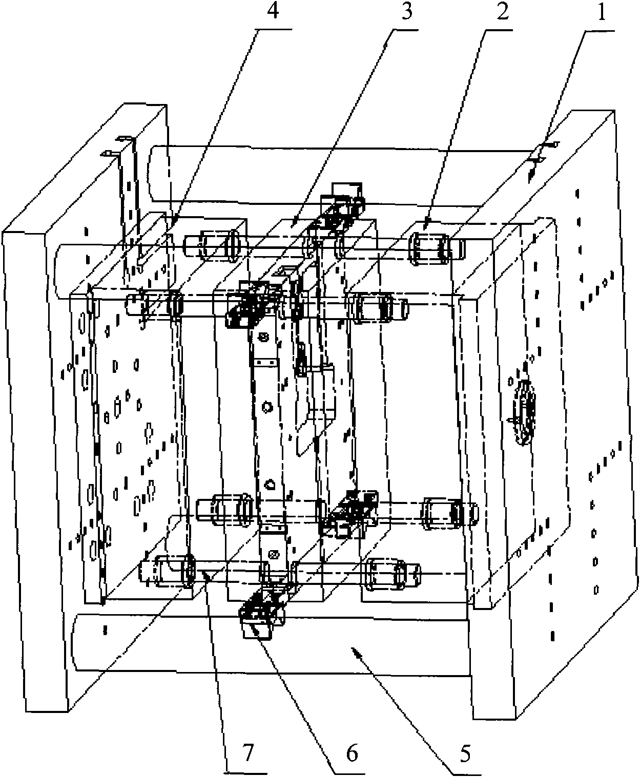
[0004] When realizing the present invention, the inventors found that the mold supporting mechanism provided by the prior art has at least the following problems: using the green column of the injection molding machine to fix the mold supporting mechanism needs to be matched with a specific type of injection molding equipment, and the accuracy of the injection molding equipment There is a certain impact; due to the load-bearing limit of using screws to fix the mold support mechanism and the green column of the injection molding machine, the mold support mechanism of this structure is only suitable for small molds such as double-layer and multi-layer molds with a weight of less than three tons. It is very large, which greatly limits the development of double-layer or multi-layer molds; moreover, it is difficult to assemble and disassemble, and it is necessary to continuously adjust the state of the mold support mechanism after loading the mold into the injection molding machine, which wastes a lot of time and causes a lot of manpower and material resources. consumption and waste

Method used


Image

  • Die and die supporting mechanism thereof
  • Die and die supporting mechanism thereof
  • Die and die supporting mechanism thereof

Examples


Embodiment 1

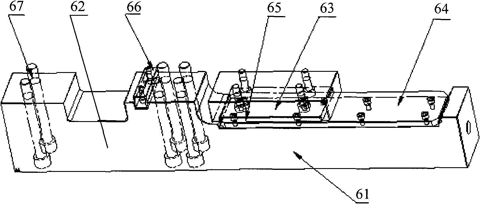
[0031] Embodiments of the present invention provide a mold support mechanism, such as figure 2 As shown, the mold support mechanism 6 includes: a support beam 61 for supporting the mold middle template; a fixing part 62 for fixing the mold front template or the mold rear template; a cushion block for fixing the mold middle template 63, set on the support beam 61.

[0032] The mold support mechanism provided in this embodiment is applied in a double-layer mold or a multi-layer mold to provide support for the middle template of the mold. Specifically, the affixed part 62 is affixed to the bottom of the mold front template or the mold rear template, The spacer 63 is fixedly connected to the middle formwork of the mold, so that the support beam 61 is under the middle formwork of the mold to provide support for the middle formwork of the mold. When the mold is opened and closed, the spacer 63 and the support beam 61 slide relative to each other to realize Support for the formwork...

Embodiment 2

[0036] On the basis of Example 1, as figure 1 As shown, during the mold opening and closing process, the cushion block 63 and the support beam 61 slide relative to each other, thereby causing the wear of the support beam 61. Therefore, further, the support beam 61 is provided with a first wear-resistant plate 64 . The first wear plate 64 has good wear resistance, and can effectively reduce wear and tear of the support beam 61 .

[0037] Still further, the first wear-resistant plate 64 may be fixedly connected to the support beam 61 through screws 67 or the like. The first wear-resistant plate 64 can be disassembled and replaced. When the first wear-resistant plate 64 is worn to the extent that it needs to be replaced, the first wear-resistant plate 64 can be replaced, which increases the service life of the entire mechanism.

[0038] Furthermore, since the cushion block 63 and the support beam 61 slide relative to each other during the mold opening and closing process, lubri...

Embodiment 3

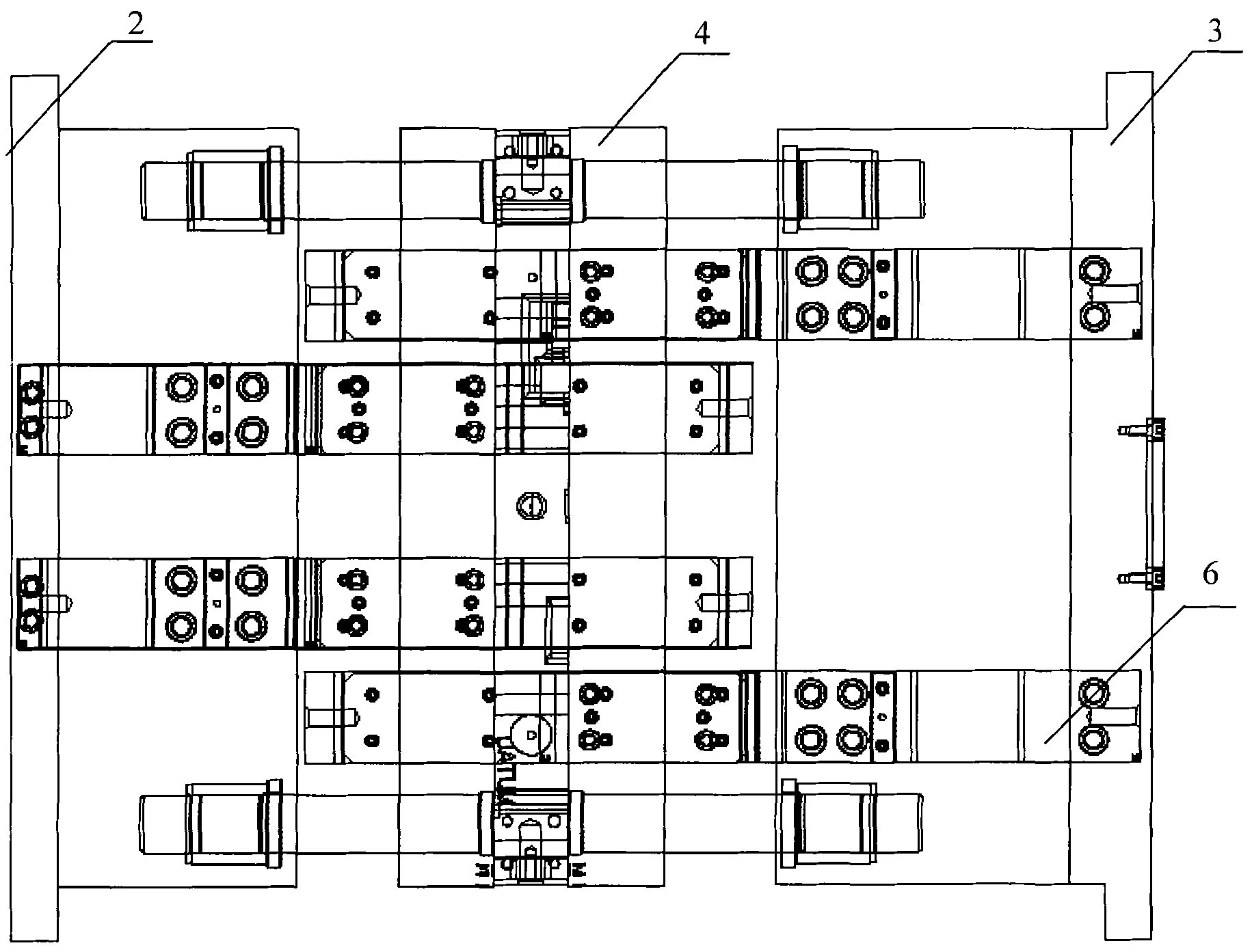
[0046] Embodiments of the present invention provide a mold, such as image 3 As shown, it includes: a mold front template 2, a mold rear template 3 and at least one mold middle template 4, and at least one mold support mechanism 6 is affixed to the mold, and the mold support mechanism includes: for supporting the middle of the mold The supporting beam of the template 4; the fixing part for fixing the front template 2 of the mold or the rear template 3 of the mold; the pad for fixing the middle template 4 of the mold is arranged on the supporting beam.

[0047] The mold provided in this embodiment is a double-layer mold or a multi-layer mold, and a mold support mechanism 6 is used to provide support for the middle template 4 of the mold. Specifically, the fixed part of the mold support mechanism 6 is fixed on the front template 2 or Below the mold rear formwork 3, the cushion block is fixedly connected with the mold middle formwork 4, so that the support beam is under the mold ...


PUM


Abstract

The embodiment of the invention discloses a die and a die supporting mechanism thereof, relating to the field of injection molding dies. The die and the die supporting mechanism have simple structures and large bearing force, and are easy to assemble and disassemble. The die supporting mechanism comprises a supporting beam, a fixedly-connected part and a cushion block, wherein the supporting beam is used for supporting a die middle template; the fixedly-connected part is fixedly connected with a die front template or a die back template; and the cushion block is fixedly connected with the die middle template, and is arranged on the supporting beam. The die comprises a die front template, a die back template and at least one die middle template, wherein the die is fixedly connected with at least one die supporting mechanism; and the die supporting mechanism comprises the supporting beam which is used for supporting the die middle template, the fixedly-connected part which is fixedly connected with the die front template or the die back template, and the cushion block which is fixedly connected with the die middle template, and is arranged on the supporting beam. The die supporting mechanism is applied to double-layer dies or multi-layer dies.

Description

technical field [0001] The invention relates to the field of injection molds, in particular to a mold and a mold support mechanism thereof. Background technique [0002] In the design of injection molds, two-layer molds or multi-layer molds are generally used to double the production efficiency. However, there is no fixed support method for the intermediate formwork in the middle of the multi-layer and double-layer molds. [0003] The existing technology provides a method of using mold guide pillars or designing an auxiliary support mechanism on the mold to realize the support of the middle part of the mold, such as figure 1 As shown, taking a double-layer mold as an example, the double-layer mold includes: a mold front template 2, a mold middle template 3 and a mold rear template 4, and a mold guide column 7 is set during the mold, and the double-layer mold is placed on two injection molding machine support plates 1, the two injection molding machine support plates 1 are ...

Claims


Application Information

Patent Timeline
IPC IPC(8): B29C45/26
Inventor 张平黄俊朱运成刘军李兴世
Owner QINGDAO HAIER MOLDS
Learn More