Method for stabilizing random drift of pulse laser beam
A technology of random drift and stable pulse, applied in lasers, laser parts, phonon exciters, etc., can solve the problems of adding new ones, and achieve the effect of easy operation, low cost and wide application range
- Summary
- Abstract
- Description
- Claims
- Application Information
AI Technical Summary
Problems solved by technology
Method used
Image
Examples
Embodiment 1
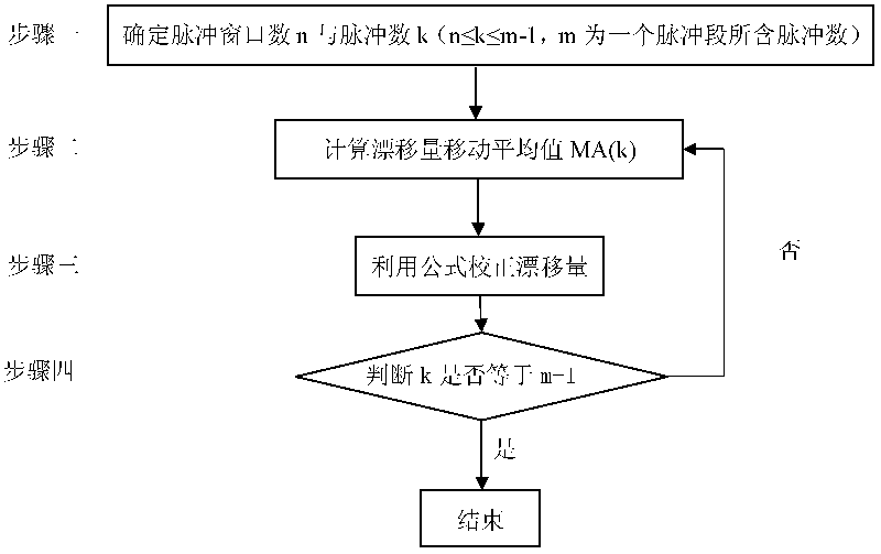
[0036] Such as figure 1 As shown, the specific steps of Embodiment 1 of the present invention are as follows:
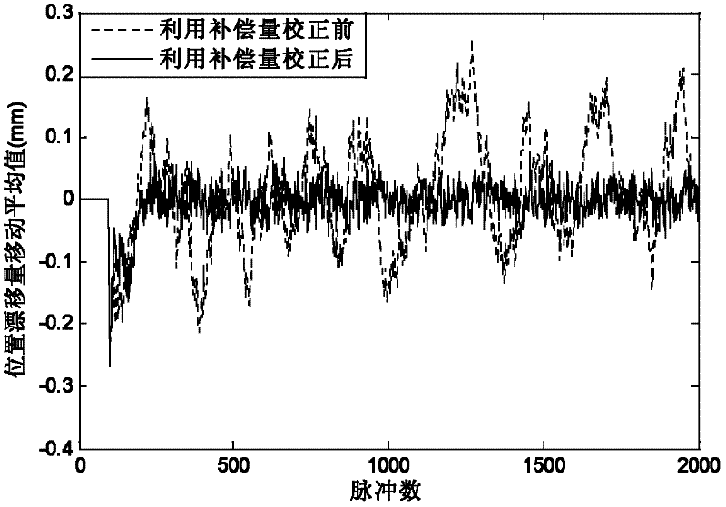
[0037] In the absence of ground jitter, when only the random drift of the laser itself is considered in this example, the wavelength of the light source, the initial geometric parameters and the drift range of the random incident pulse are known: the wavelength of the light source is 632.8 nm, the beam propagation distance is 10 meters, and the position of the incident pulse drifts [ -0.1, 0.1] millimeters, pointing drift [-0.2, 0.2] milliradians, the number of pulses m in the pulse segment (m is a positive integer), m=2000 in this example;
[0038] Step 1 determines the number of pulse windows n and the number of pulses k (n, k is a positive integer, and n≤k≤m-1), in this example n=100, k=100;
[0039] Step 2 Calculate the moving average of the drift of the first 100 pulses according to the following formula of the moving average of the drift, and use this value as...
Embodiment 2
[0049] The concrete steps of embodiment 2 of the present invention are as follows:
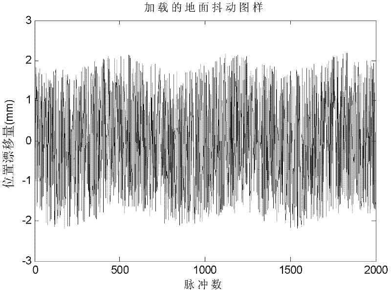
[0050] Vibration from the ground can cause optical components to vibrate and also affect beam stability. In order to compare the influence of ground jitter on the correction beam pointing drift, the correction pattern after loading the ground turbulence is now considered. The loaded ground disturbance is set as a sinusoidal drift, such as image 3 shown;
[0051] Known light source wavelength, initial geometric parameters and random incident pulse drift range: light source wavelength 632.8 nm, beam propagation distance 10 meters, incident pulse position drift [-0.1, 0.1] mm, pointing drift [-0.2, 0.2] milliradians, pulse The number of pulses m in the segment (m is a positive integer), in this example m = 2000;
[0052] Step 1 determines the number of pulse windows n and the number of pulses k (n, k is a positive integer, and n≤k≤m-1), in this example n=100, k=100;
[0053] Step 2 Calculate t...
Embodiment 3
[0063] The concrete steps of embodiment 3 of the present invention are as follows:
[0064] In the absence of ground jitter, when only the random drift of the laser itself is considered in this example, the wavelength of the light source, the initial geometric parameters and the drift range of the random incident pulse are known: the wavelength of the light source is 325 nm, the beam propagation distance is 15 meters, and the position of the incident pulse drifts [ -0.2, 0.2] millimeters, pointing drift [-0.1, 0.1] milliradians, the number of pulses in the pulse segment m (m is a positive integer), m=5000 in this example;
[0065] Step 1 determines the number of pulse windows n and the number of pulses k (n, k is a positive integer, and n≤k≤m-1), in this example n=200; k=200;
[0066] Step 2 Calculate the moving average of the drift of the first 200 pulses according to the following formula of the moving average of the drift, and use this value as the first group of moving ave...
PUM
 Abstract
Description
Claims
Application Information
 - R&D
- Intellectual Property
- Life Sciences
- Materials
- Tech Scout
- Unparalleled Data Quality
- Higher Quality Content
- 60% Fewer Hallucinations
Browse by: Latest US Patents, China's latest patents, Technical Efficacy Thesaurus, Application Domain, Technology Topic, Popular Technical Reports.
© 2025 PatSnap. All rights reserved.Legal|Privacy policy|Modern Slavery Act Transparency Statement|Sitemap|About US| Contact US: help@patsnap.com


