
Display method of tempered martensitic steel carbide colour metallography and electrothermal metallographic chromogenic device special for display method

A technique for tempering martensite and color metallography, which is used in electrothermal metallographic color developing devices, and the display field of tempered martensitic steel carbide color metallography, which can solve the problem of heating color and resistance of samples that cannot be inspected on site. The furnace temperature control accuracy is low, the resistance furnace heating is inconvenient to move, etc., to achieve the effect of automatic control of heating temperature and holding time, automatic control of heating temperature and time, and light weight

Active Publication Date: 2012-02-29
ELECTRIC POWER RES INST OF GUANGDONG POWER GRID +1
View PDF3 Cites 11 Cited by
  • Summary
  • Abstract
  • Description
  • Claims
  • Application Information

AI Technical Summary

Problems solved by technology

[0007]In addition, under normal circumstances, the heating metallographic structure color development device of the thermal dyeing method adopts the resistance furnace for ordinary heat treatment, but the resistance furnace is used for the thermal dyeing method. The following shortcomings: (1) The resistance furnace is composed of electric heating elements, masonry, metal shell, furnace door and electrical control system. Inconvenient; (2) Resistance furnaces are divided into low-temperature furnaces with a working temperature below 650°C, medium-temperature furnaces with a working temperature of 650-1000°C, and high-temperature furnaces with a working temperature above 1000°C. The heating temperature less than or equal to 500°C is high, and the temperature control accuracy of the ordinary resistance furnace is low within the temperature range of the thermal dyeing method, and the error is large; (3) The oxidation film during the heating and color development process cannot be directly observed by the resistance furnace heating color development Changes in color; (4) Resistance furnace heating is not easy to move, and it is impossible to heat and develop the color of on-site metallographic inspection samples; (5) The current resistance furnace needs manual control of heating time, which is difficult to control the experimental effect

Method used


Image

  • Display method of tempered martensitic steel carbide colour metallography and electrothermal metallographic chromogenic device special for display method
  • Display method of tempered martensitic steel carbide colour metallography and electrothermal metallographic chromogenic device special for display method
  • Display method of tempered martensitic steel carbide colour metallography and electrothermal metallographic chromogenic device special for display method

Examples


Embodiment 1

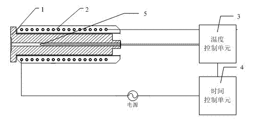
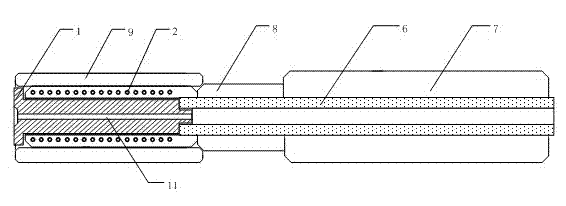
[0053] Figure 1~2 The electrothermal metallographic device shown is an embodiment of the present invention. The electrothermal metallographic color development device consists of a heat-insulating handle, a heat-dissipating jacket 8, a heat-insulating shell 9, a temperature measuring device 5, a heater, a temperature control unit 3 for controlling the heating temperature of the heater temperature, and a time for controlling the heating time. The control unit 4 constitutes. The heater, the temperature control unit 3 and the time control unit 4 are respectively connected to the power supply. The heating temperature controlled by the temperature control unit 3 ranges from 100 to 600°C. The temperature control unit 3 is electrically connected to the time control unit 4, and the output control terminal of the temperature control unit 3 is connected to the input control terminal of the heater for timely controlling the opening and closing of the electric heater. The heater is co...

Embodiment 2

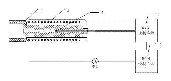
[0057] The difference from Embodiment 1 is: as Figure 3~4 As shown, the working end of the heating element 1 of the electrothermal metallographic color development device is cylindrical, in which the hollow chamber is used to place metal samples, and is used for metal color metallographic samples with a grinding surface diameter φ≤15mm, and the hollow chamber is open A piece of quartz glass sheet 10 slightly larger than its diameter can be covered at the place for heat preservation and observation.

Embodiment 3

[0060] (1) For the tempered martensitic steel T91 steel sample after 85,000 hours of high temperature operation, the smooth grinding surface was trimmed with a grinding wheel, and then coarsely ground with No. 120 and No. 240 coarse sandpaper, and then successively with No. No., No. 1500 and No. 2000 metallographic sandpapers are used for fine grinding. Every time the sandpaper is changed during grinding, the grinding direction of the T91 steel sample should be perpendicular to the direction of the previous grinding mark. Grind until the last grinding mark is removed to fully remove the deformed layer. And the new wear marks are even and consistent. When grinding, the pressure should not be too high, especially when the last sandpaper is ground, it must be lightly ground.

[0061] Wipe the finely ground T91 steel sample with absolute ethanol, move it to a polishing disc equipped with woolen cloth, nylon silk, velvet or other velvet with fine and uniform fibers, and polish it...


PUM


Abstract

The invention discloses a display method of tempered martensitic steel carbide colour metallography, comprising the following steps of: (1) grinding and polishing the surface of a tempered martensitic steel sample to obtain a tempered martensitic steel metallographic sample; (2) heating the tempered martensitic steel metallographic sample in the oxidation atmosphere to 400-500 DEG C, keeping warm for 6-15 minutes, and forming an interference oxide-film, which makes the microstructure of metal and alloy to present different colors by the action of light, on the surface of the tempered martensitic steel sample, so as to display the tempered martensitic steel carbide color metallography. The method provided by the invention can be used to effectively display and raise the contrast between the T91 steel carbide and the matrix microstructure, so as to effectively observe the microstructure form of the martensitic steel.

Description

technical field [0001] The invention relates to a method for displaying colored metallographic phases of steel carbides, belonging to the technical field of metallographic sample preparation, in particular to a method for displaying colored metallographic phases of tempered martensitic steel carbides. The invention also relates to an electrothermal metallographic color development device dedicated to the method. Background technique [0002] After long-term high-temperature operation of high-temperature metal parts in power stations, the metal materials of these parts will undergo continuous aging of the microstructure and gradual deterioration of macroscopic properties. It has important theoretical value and practical significance to grasp the quality status of high-temperature metal parts, reduce various accidents caused by material aging during operation, and improve the reliability of safe operation of high-temperature metal parts. At present, the structural aging inspe...

Claims


Application Information

Patent Timeline
IPC IPC(8): G01N1/31G01N1/44G01N1/32
Inventor 钟万里王伟李正刚
Owner ELECTRIC POWER RES INST OF GUANGDONG POWER GRID
Learn More