


Quick Research
Generate reliable direction feasibility study reports for your R&D in just a few steps.

Technical Q&A
Discover and master advanced knowledge NOW. Basics, ideas, possibilities, all at once.

Find Solutions
As an expert in R&D theories, this can generate solutions to your technical problems instantly.

Evaluate Feasibility
Analyze your overall solution with one click, know your potential R&D risks in advance.

Monitor Landscape
Get weekly tech updates, stay abreast of the latest tech innovations and key insights.
Hot-shaft mixing drying process and device
A drying equipment and heat shaft technology, applied in lighting and heating equipment, drying solid materials, non-progressive dryers, etc., can solve the problems of high operating cost, high drying energy consumption, difficult application in the environmental protection industry, etc. speed, reduce auxiliary equipment, and facilitate the effect of large-scale production and manufacturing
- Summary
- Abstract
- Description
- Claims
- Application Information
AI Technical Summary
Problems solved by technology
Method used
Image

Examples
Embodiment 1
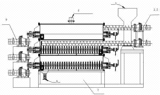
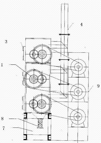
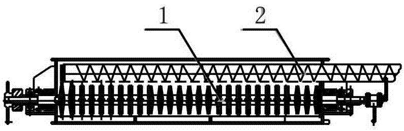
[0047] Example 1 :Such as figure 1 , 2 , 3, and 4 are a kind of thermal shaft mixing drying equipment used for drying paste-like materials. It consists of a three-layer three-stage mixing drying structure. The upper layer and the middle layer are pre-drying unit layers, and the lower layer is refined. Dry the cell layer. The pre-drying unit layer is a screw feeding system. The drying unit layer is composed of two hollow blade shafts (1) with hollow blades installed in a square casing and a screw feeding mechanism. The two axially parallel hollow blade shafts ( The hollow blades (10) on 1) intersect each other, and the screw distributing device (2) above the two hollow blade shafts (1) is composed of one end of the distributing screw shaft (2.1) connected to the distributing motor (2.2), and the distributing screw shaft (2.1) is located centrally above the two hollow blade shafts (1). The feeding port (5) of the wet material is located above one end of the screw distribut...
Embodiment 2
[0052] Embodiment two: Such as Figure 5 , 6 As shown in , 7, it is a kind of thermal shaft mixing drying equipment applied to the drying of liquid materials. It is composed of three layers and three stages of mixing drying structure. The upper layer and the middle layer are pre-drying unit layers, and the lower layer is refined drying unit layer. The pre-drying unit layer is a sports car feeding system. The drying unit layer is composed of two hollow blade shafts (1) with hollow blades (10) in the rectangular housing (3) and a reciprocating sports car feeding device (6). The hollow vanes (10) on the two axially parallel hollow vane shafts (1) intersect, and the sports car feeding device (6) above the two hollow vane shafts (1) is composed of the feeding sports car (6.1), sports car slide The channel (6.2) is composed of a feeding pipeline, and a distributing nozzle is arranged on the feeding pipeline.
[0053] When working, the bottom material is added to the upper layer ...
PUM
 Abstract
Description
Claims
Application Information
 - R&D Engineer
- R&D Manager
- IP Professional
- Industry Leading Data Capabilities
- Powerful AI technology
- Patent DNA Extraction
Browse by: Latest US Patents, China's latest patents, Technical Efficacy Thesaurus, Application Domain, Technology Topic, Popular Technical Reports.
© 2024 PatSnap. All rights reserved.Legal|Privacy policy|Modern Slavery Act Transparency Statement|Sitemap|About US| Contact US: help@patsnap.com