
Self-riveting iron core transformer

An iron core transformer, self-riveting technology, applied in the field of transformers, can solve problems such as cumbersome, rough surface of the iron core, influence on the electrical performance of the iron core, etc., and achieve the effect of smooth surface, good electrical performance consistency, and good electrical performance

Inactive Publication Date: 2012-02-22
SUZHOU KANGKAI ELECTRIC
View PDF3 Cites 4 Cited by
  • Summary
  • Abstract
  • Description
  • Claims
  • Application Information

AI Technical Summary

Problems solved by technology

This method is cumbersome during assembly, and the surface of the iron core formed after riveting is not smooth, which will affect the electrical properties of the iron core

Method used


Image

  • Self-riveting iron core transformer
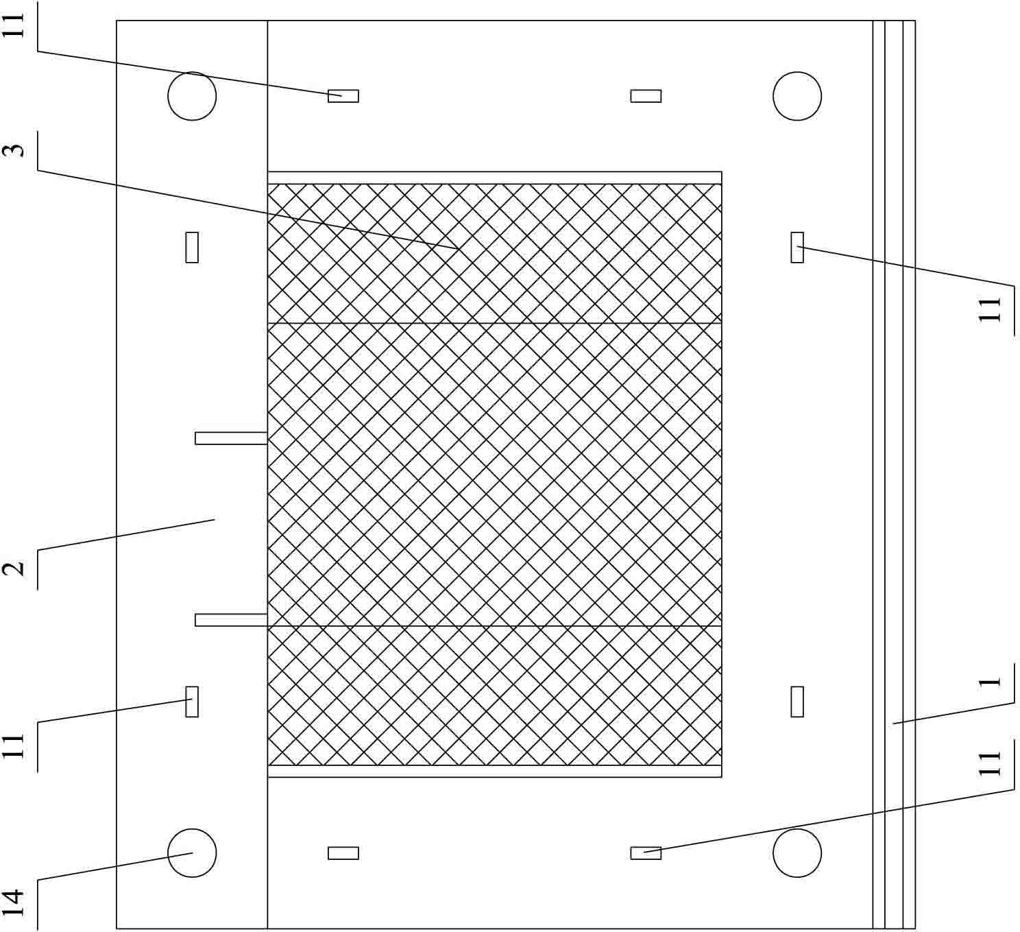
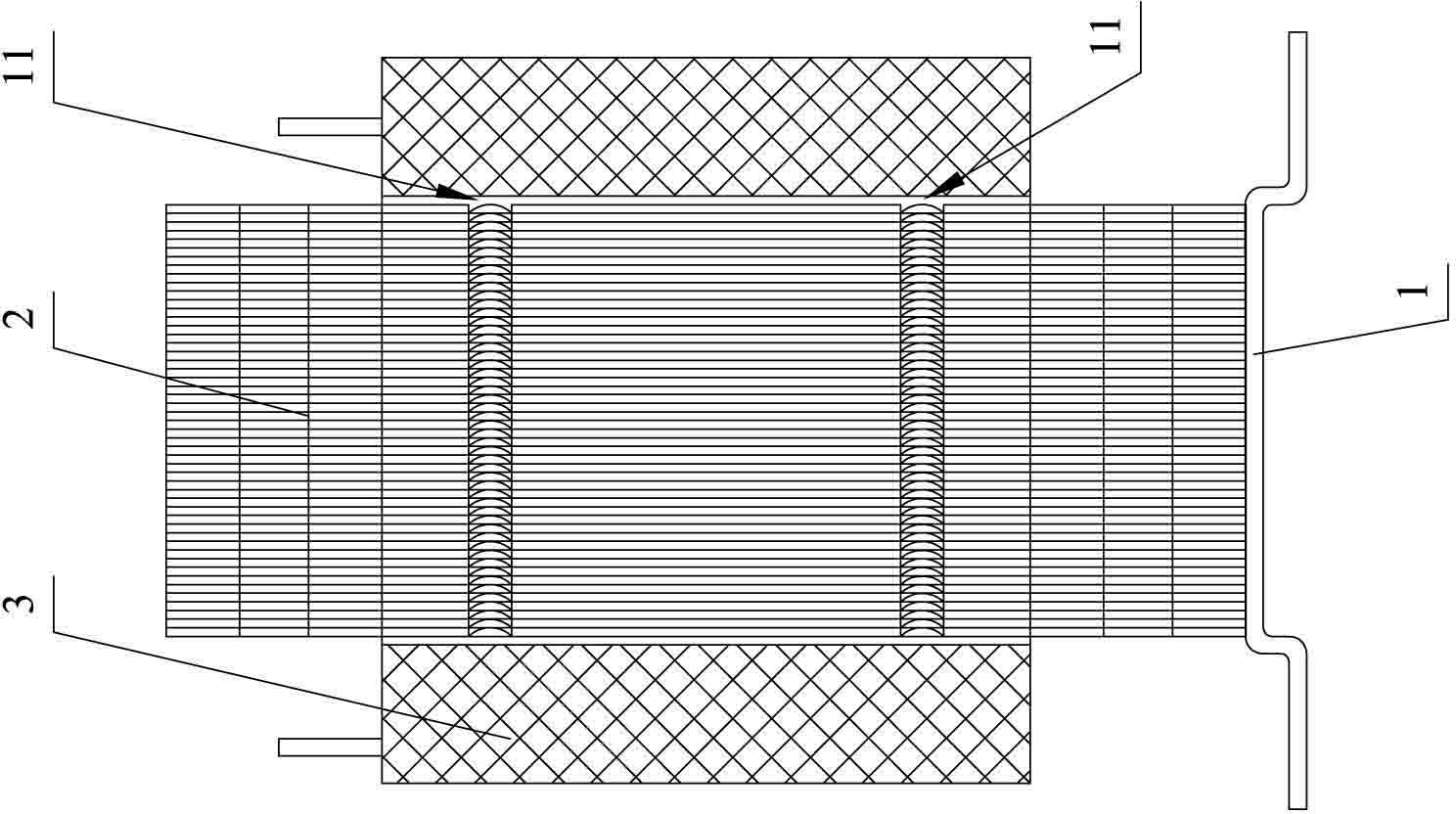
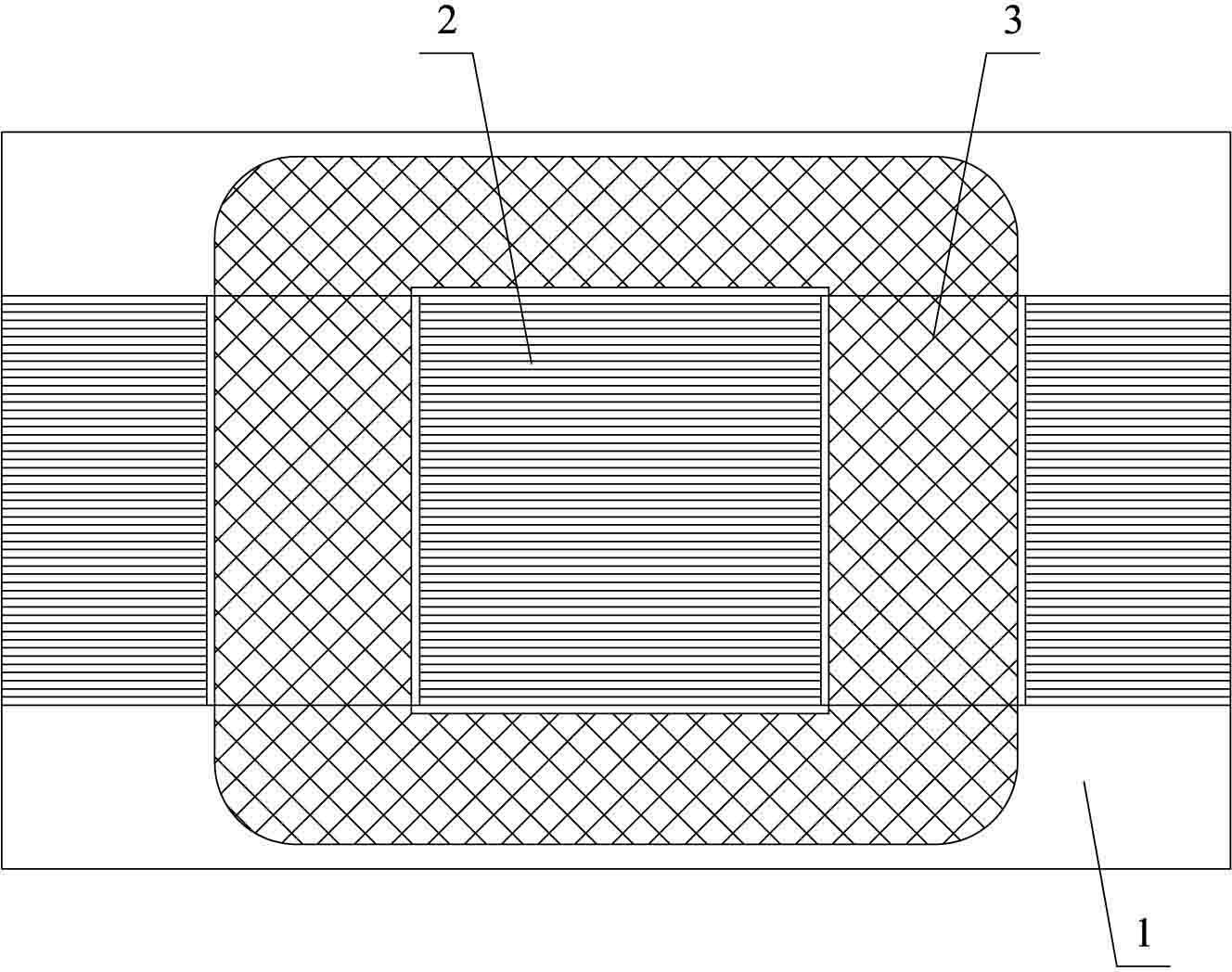
  • Self-riveting iron core transformer
  • Self-riveting iron core transformer

Examples


Embodiment 1

[0021] Embodiment one: see attached figure 1 to attach image 3 shown.

[0022] A self-riveting iron core transformer includes a support 1 , an iron core 2 arranged on the support 1 , and a coil 3 wound on the iron core 2 . The iron core 2 is formed by overlapping and riveting several silicon steel sheets, and the silicon steel sheets are self-riveting silicon steel sheets.

[0023] See attached Figure 4 And attached Figure 5 shown. The self-riveting silicon steel sheet is in the shape of "day" and adopts the combination form of "EI". It includes a central column sheet 5, two side column sheets 6 symmetrically arranged on both sides of the central column sheet 5, a first connecting portion 7 and a second connecting portion connecting the two ends of the central column sheet 5 and the side column sheets 6 8. The self-riveting silicon steel sheet has an opposite first surface 9 and a second surface 10, and a plurality of riveting buckles 11 are symmetrically punched on ...


PUM


Abstract

The invention relates to a self-riveting iron core transformer. The self-riveting iron core transformer comprises an iron core which is formed by overlapping and riveting a plurality of self-riveting silicon steel sheets, wherein each self-riveting silicon steel sheet is provided with a first surface and a second surface, and riveting buckles are punched on the first surface and the second surface; the riveting buckles comprise first riveting surfaces which are formed on the first surface and are concaved on the first surface and second riveting surfaces which are formed on the second surface and are convex on the second surface; the first riveting surfaces are arranged into grooves which are concaved on the first surface; and the second riveting surfaces are arranged into bulges which are convex on the second surface; the first riveting surfaces and the second riveting surfaces have the same shape; the bulges of the first self-riveting silicon steel sheet are clamped into the grooves of the second self-riveting silicon steel sheet during riveting; and the first riveting surfaces of the first self-riveting silicon steel sheet are tightly pressed on the second riveting surfaces of the second self-riveting silicon steel sheet. In the transformer, the iron core is formed by riveting the self-riveting silicon steel sheets, so that the transformer is convenient and fast for assembling, and the assembled transformer has relatively high electrical property.

Description

technical field [0001] The invention relates to a transformer. Background technique [0002] In the prior art, the iron core of a transformer is usually formed by overlapping multiple silicon steel sheets, and riveting holes are opened on the silicon steel sheets, and the multiple silicon steel sheets are riveted together through the riveting holes. This method is cumbersome during assembly, and the surface of the iron core formed after riveting is not smooth, which will affect the electrical properties of the iron core. Contents of the invention [0003] The purpose of the present invention is to provide a self-riveting iron core transformer with quick assembly and good electrical performance. [0004] In order to achieve the above object, the technical scheme adopted in the present invention is: [0005] A self-riveting iron core transformer, comprising an iron core, the iron core is formed by overlapping and riveting several silicon steel sheets, the silicon steel she...

Claims


Application Information

Patent Timeline
Patent Type & Authority Applications(China)
IPC IPC(8): H01F27/26H01F27/245
Inventor 沈永福
Owner SUZHOU KANGKAI ELECTRIC
Learn More