
Power socket connector and conductive terminals thereof

A technology for power sockets and conductive terminals, which is applied in the direction of contact parts, bases/shells, etc., and can solve problems such as abnormal operation of computers, insufficient clamping force, and potential safety hazards

Inactive Publication Date: 2012-02-15
SUYING ELECTRCNICS (DONG GUAN) CO LTD
View PDF14 Cites 3 Cited by
  • Summary
  • Abstract
  • Description
  • Claims
  • Application Information

AI Technical Summary

Problems solved by technology

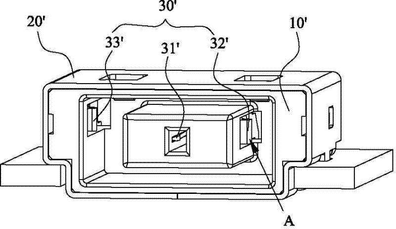
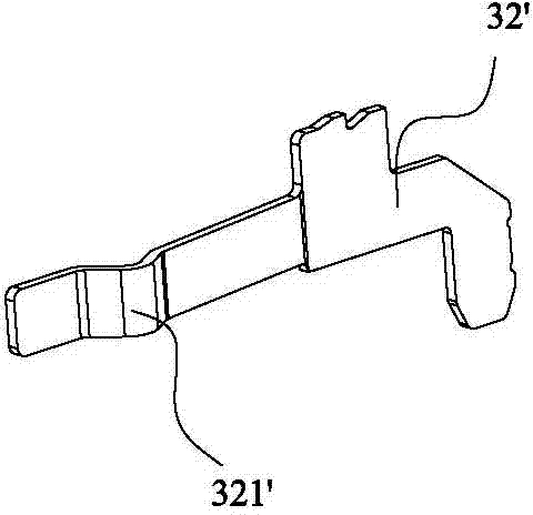
[0004] The use of this existing power socket connector relies on the vertical elastic contact portion 321' of the sheet-shaped first conductive terminal 32' to contact the docked power plug (not shown), and has the following disadvantages: 1. This The sheet-shaped first conductive terminal 32' has only a single contact point of the vertical elastic contact part 321'. If a single contact point fails, the quality will be abnormal, which will affect the stability of the current conduction, and the computer cannot operate normally; 2. If the current flow Insufficient contact points will easily cause the connector to be overheated and burn out, which will bring potential safety hazards; 3. The long-term elastic deformation of the sheet-shaped first conductive terminal 32' will easily lead to elastic recovery failure, resulting in insufficient clamping force and poor contact.

Method used


Image

  • Power socket connector and conductive terminals thereof
  • Power socket connector and conductive terminals thereof
  • Power socket connector and conductive terminals thereof

Examples


Embodiment Construction

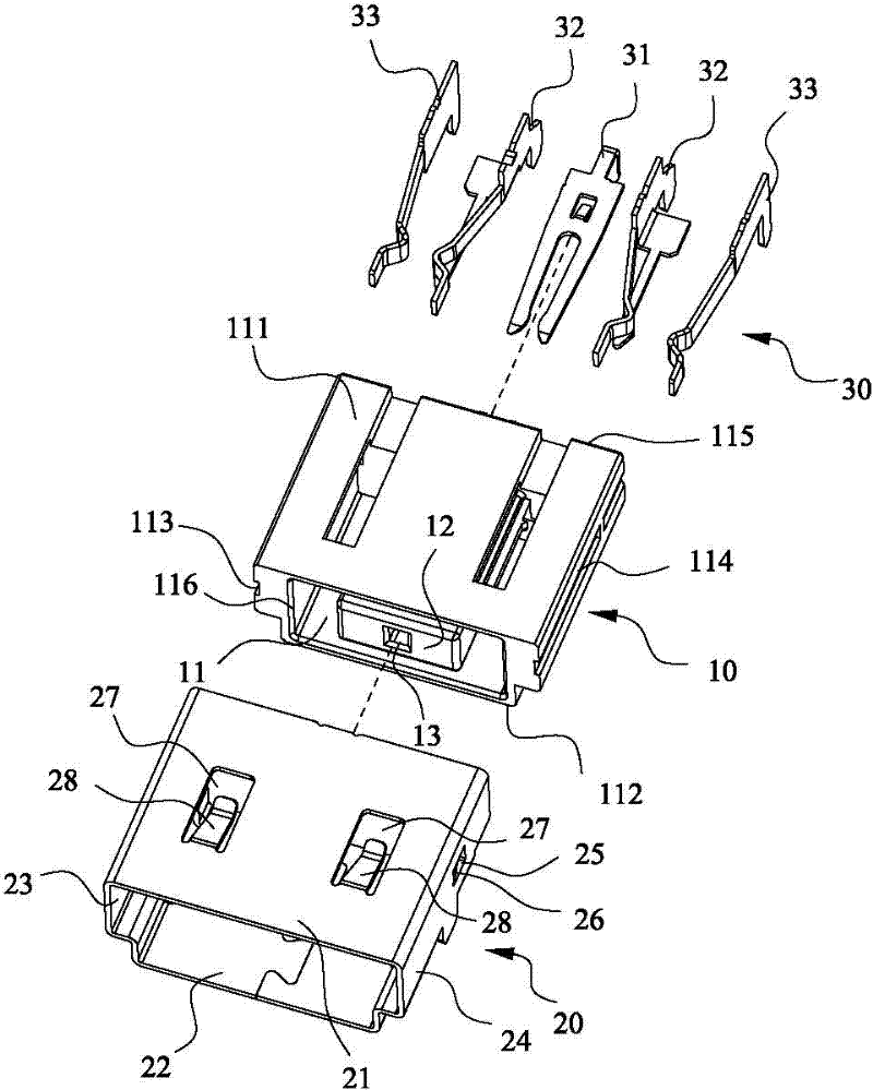
[0052] First, please refer to Figure 3 to Figure 9 As shown, it shows the specific structure of the preferred embodiment of the present invention, which includes an insulating body 10 , a shielding shell 20 covering the insulating body 10 and a terminal group 30 installed in the insulating body 10 .

[0053]Wherein, the insulating body 10 is made of plastic material, and has an accommodating space 11 for inserting a matching power plug (not shown), the accommodating space 11 is composed of a top wall 111 , a bottom wall 112 , and a left side wall 113 , a right side wall 114 and a rear end surface 115 , and the front end of the accommodating space 11 is an opening 116 . In addition, a tongue plate 12 extends from the rear end surface 115 of the insulating body 10 , and a central insertion slot 13 penetrating through the rear end surface 115 of the insulating body 10 is provided on the front end surface of the tongue plate 12 . There are first insertion slots 14 located on the...


PUM


Abstract

The invention discloses a power socket connector. The power socket connector comprises: an insulation body; a shielding housing, which coats an outer surface of the insulation body; and a terminal set, which is installed in the insulation body. The terminal set includes a central contact terminal and conductive terminals, which are at two sides of the central contact terminal; a vertical type elastic contact part and a horizontal type elastic part are arranged on the same conductive terminal; and the vertical type elastic contact parts and the horizontal type elastic parts are respectively connected to an L-shaped holding portion through a vertical connection portion and a horizontal connection portion. Therefore, when a butted power plug is inserted into the power socket connector, the vertical type elastic contact parts and the horizontal type elastic parts simultaneously make contacts with the butted power plug, so that an area for passing of a high current is enlarged and stability of current conduction is improved; besides, an occurrence of burning out of the connector due to high temperature can be avoided, wherein the high temperature is caused by insufficient of contact points during current flowing; and thus the product security during high currents can be ensured, hidden troubles are eliminated, and operating life of the connector is also extended.

Description

technical field [0001] The invention relates to the technical field of power socket connectors, in particular to a power socket connector with multiple terminal contact points and stable current conduction. Background technique [0002] With the popularization and application of notebook computers, in order to realize the expected functions, it is necessary to provide sufficient power to the notebook computer under continuous long-term operating conditions to meet the uninterrupted work of the notebook computer for a long period of time. Therefore, one end of the notebook computer must have a socket connector to connect to the power supply to realize it. [0003] The existing power socket connector structure can refer to figure 1 As shown, the power socket connector includes an insulating body 10', a terminal group 30' installed in the insulating body 10', and a shielding shell 20' covered outside the insulating body 10', facing the rear surface of the insulating body 10'. ...

Claims


Application Information

Patent Timeline
IPC IPC(8): H01R13/11H01R13/46
Inventor 蔡佳谚孔国齐
Owner SUYING ELECTRCNICS (DONG GUAN) CO LTD
Learn More