
Vehicle failure remote diagnostic method based on in-vehicle information terminal

A vehicle information terminal, vehicle failure technology, applied in the direction of electrical testing/monitoring, etc., can solve the problems of time delay, driving to the auto repair shop, vehicle and personnel safety consequences, etc., to save time and effort in detection, and reduce cables connection, reducing the effect of battery power

Inactive Publication Date: 2012-02-15
北京航天科工世纪卫星科技有限公司
View PDF4 Cites 4 Cited by
  • Summary
  • Abstract
  • Description
  • Claims
  • Application Information

AI Technical Summary

Problems solved by technology

[0003] 1. With the development of my country's automobile industry, there are more and more vehicles, and vehicle maintenance and maintenance are becoming more and more important. The traditional detection method is that when the vehicle has a fault alarm or abnormal situation, the user must drive the car to a professional vehicle In the inspection field or auto repair shop, only professional equipment can be used to inspect the vehicle. The owner will not only spend a lot of inspection fees, but also delay a lot of time.
[0004] 2. With the emergence of automotive consumer electronics products, many cars are now equipped with on-board computers, which have functions such as entertainment, navigation, reversing images, and wireless Internet access, but they do not provide vehicle fault detection and data transmission functions.
When the vehicle breaks down or is in an abnormal situation, the owner cannot accurately know the current condition of the vehicle, and cannot drive the car to the auto repair shop in time, except that the car itself has some alarm prompts. cause serious consequences

Method used


Image

  • Vehicle failure remote diagnostic method based on in-vehicle information terminal
  • Vehicle failure remote diagnostic method based on in-vehicle information terminal
  • Vehicle failure remote diagnostic method based on in-vehicle information terminal

Examples


Embodiment Construction

[0017] The present invention will be further described below in conjunction with the accompanying drawings.

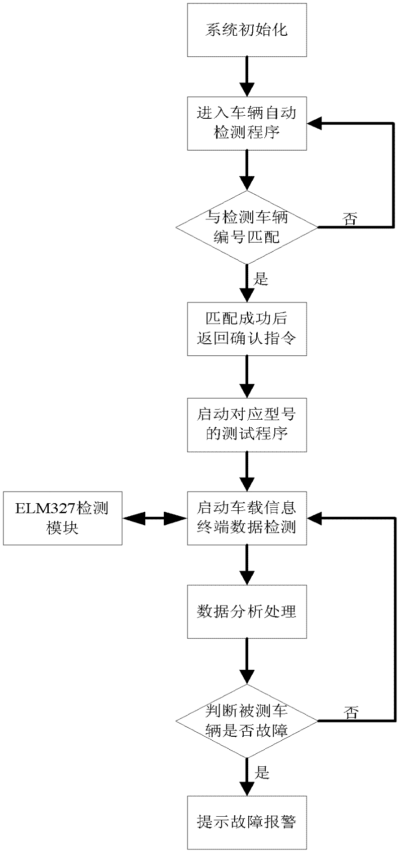
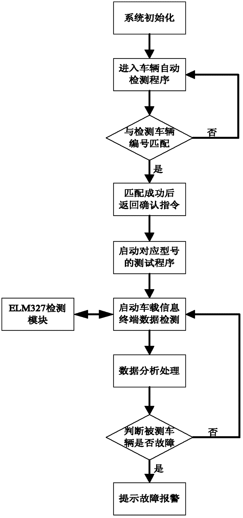
[0018] Such as figure 1 As shown, the pairing of the Bluetooth device and the matching of the vehicle under test. After connecting the ELM327 Bluetooth detection device to the vehicle under test, the Bluetooth module of the vehicle information terminal is paired with the detection module. After the device is connected correctly, search for the vehicle under test and select the corresponding vehicle model. Match with it; start the vehicle detection program, start the vehicle detection program after the matching is successful, detect one by one according to the serial number of the vehicle fault code, and send the detection data to the center; data processing, the central computer performs data analysis after receiving the data, if any Failure, the central computer sends an alarm message to prompt the owner.

[0019] Such as figure 2 As shown, the present invention us...


PUM


Abstract

The invention relates to a vehicle failure remote diagnostic method based on in-vehicle information terminal equipment, and belongs to the field of in-vehicle information failure diagnosis. The method comprises the following steps of: firstly, matching Bluetooth equipment and matching a tested vehicle: matching a Bluetooth module of an in-vehicle information terminal with a detection module after ELM327 Bluetooth detection equipment is connected with the tested vehicle, searching the tested vehicle after correct connection of the equipment, and selecting a responding vehicle model and matching the responding vehicle model with the tested vehicle; secondly, starting a detection program of the vehicle after successful matching, detecting one by one according to a serial number sequence of vehicle failure codes, and sending detection data to a center; and finally, performing processed data analysis by a central computer after the central computer receives the data, and sending a warning message to prompt a vehicle owner by the central computer if failure exists. By the method, the failure condition of the vehicle is remotely detected by a management center, and the state information of the vehicle is fed back to a user in real time.

Description

technical field [0001] The method relates to a vehicle fault remote diagnosis method based on vehicle-mounted information terminal equipment, and belongs to the field of vehicle-mounted information fault diagnosis. Background technique: [0002] For traditional vehicle fault detection methods, there are mainly the following deficiencies: [0003] 1. With the development of my country's automobile industry, there are more and more vehicles, and vehicle maintenance and maintenance are becoming more and more important. The traditional detection method is that when the vehicle has a fault alarm or abnormal situation, the user must drive the car to a professional vehicle Only professional equipment can be used in inspection field or auto repair shop to inspect vehicles, and the owner will not only spend a lot of inspection fees, but also delay a lot of time. [0004] 2. With the emergence of automotive consumer electronics products, many cars are now equipped with on-board comput...

Claims


Application Information

Patent Timeline
Patent Type & Authority Applications(China)
IPC IPC(8): G05B23/02
Inventor 高鹏蒋朝连宋浩王锦华宝洪刁建新李洁
Owner 北京航天科工世纪卫星科技有限公司
Learn More