Folding-type microchannel porous flat pipe and molding method thereof

A molding method and micro-channel technology, applied in the direction of tubular elements, lighting and heating equipment, heat exchange equipment, etc., can solve the problem that the heat exchange equipment cannot meet the application system well, so as to improve product turnover efficiency and reduce inventory , good effect of pressure resistance

Inactive Publication Date: 2012-02-15
YANGJIANG BAOMALI AUTO AIR CONDITIONER
View PDF2 Cites 22 Cited by
  • Summary
  • Abstract
  • Description
  • Claims
  • Application Information

AI Technical Summary

Problems solved by technology

[0002] At present, with the miniaturization of mechatronic systems and chemical mechanical systems, traditional heat exchange equipment can no longer meet the basic requirements of application systems. The development of miniaturization of heat exchange equipment has become an urgent requirement and an inevitable trend. On the other hand, with the increasingly prominent energy problems, it is required to reduce the volume of heat exchange equipment as much as possible under the premise of satisfying heat exchange, that is, to improve the compactness of heat exchange equipment, thereby reducing the weight of heat exchange equipment and saving materials. , and correspondingly improve the space utilization
A key technology for the miniaturization of heat exchange equipment is the miniaturization and high efficiency of heat exchange flat tubes. It is difficult for existing heat exchange flat tubes to meet this development requirement, so it is necessary to make corresponding technical improvements.

Method used


Image

  • Folding-type microchannel porous flat pipe and molding method thereof
  • Folding-type microchannel porous flat pipe and molding method thereof
  • Folding-type microchannel porous flat pipe and molding method thereof

Examples


Embodiment Construction

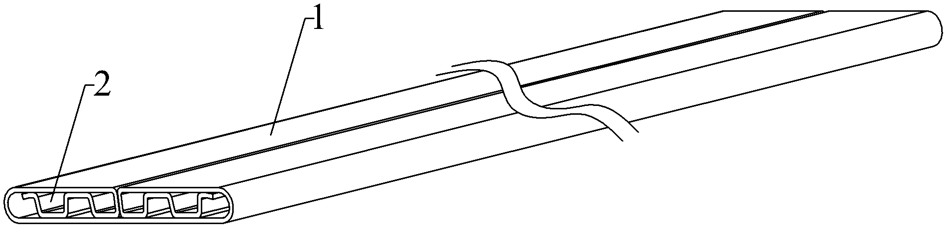
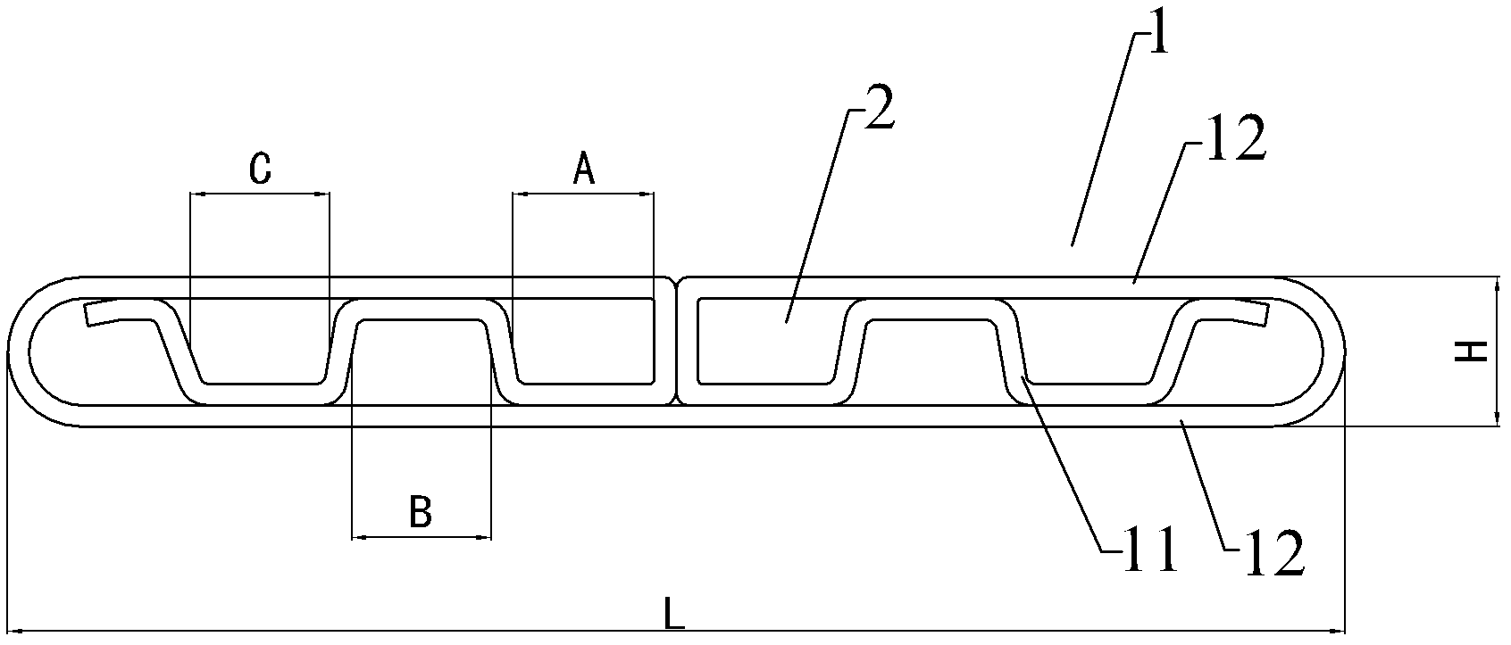
[0026] Such as figure 1 , 2 As shown, the foldable microchannel porous flat tube of the present invention is integrally formed by folding the two ends of a single thin plate 1 through several roundabouts, and its cross-section is flat oval, including several roundabouts. The pores 2 formed by folding and spaced apart from each other.

[0027] The above-mentioned single sheet 1 is made of aluminum platinum plate, which is divided into a roundabout bending part 11 and an embedding part 12. The flat tube pores 2 are bent and folded by the roundabout bending part 11 of the single sheet 1 and then folded and folded with the single sheet 1 The embedding portion 12 is welded and fixed, and the upper and lower planes of the detour bending portion 11 are respectively seamlessly brazed and hermetically connected to the plane of the embedding portion 12. The tortuous bending portion 11 forms a partition plate between the flat tube pores 2 to enhance the plane compressive strength of the por...


PUM

PropertyMeasurementUnit
lengthaaaaaaaaaa
widthaaaaaaaaaa
lengthaaaaaaaaaa

Abstract

The invention discloses a folding-type microchannel porous flat pipe and a molding method thereof. The flat pipe is formed by subjecting a single thin slab to integral molding, and the single thin slab is sequentially advanced by a mechanical bending mechanism in a multi-point molding control manner, wherein two ends of the single thin slab are respectively bent circuitously, then the circuitously bent parts are vertically bent twice and then horizontally turned and folded once and are butt-jointed at a mesal position of the single thin slab for integral molding, and thus, a porous flat pipe with mutually spaced fine pores is further formed. Compared with the prior art, the invention has the beneficial effects that: 1, the structural form of the flat pipe disclosed by the invention is suitable to being used in a light-weight heat exchanger with light weight and high heat conductivity; 2, the advantages of compact entire structure, high heat exchange efficiency, light weight, firmness, durability, and operation safety and reliability are achieved; 3, by adopting the integral folding and molding structure, the energy consumption of a product production process is low, and the pressure resistance of products is good; and 4, the effect of producing and yield can be achieved through mechanical control, the inventory level is greatly reduced, the product turnover efficiency is increased, and the requirement on lean production can be met.

Description

Technical field [0001] The invention relates to a flat tube, which belongs to the technical field of flat tubes for heat exchangers, in particular to a folded microchannel porous flat tube and a forming method thereof. Background technique [0002] At present, with the miniaturization of mechatronic systems and chemical mechanical systems, traditional heat exchange equipment can no longer meet the basic requirements of the application system. The development of miniaturization of heat exchange equipment has become an urgent requirement and an inevitable trend. ; On the other hand, as energy issues become increasingly prominent, it is required that the volume of heat exchange equipment must be reduced as much as possible on the premise of meeting heat exchange, that is, to improve the compactness of heat exchange equipment, thereby reducing the weight of heat exchange equipment and saving materials , And improve space utilization accordingly. A key technology in the development o...

Claims


Application Information

Patent Timeline
Patent Type & Authority Applications(China)
IPC IPC(8): F28F1/02F28F9/22B21D11/10B21D53/06
Inventor 陈基镛江春燕谢繁华陈洁清关活陈兆强
Owner YANGJIANG BAOMALI AUTO AIR CONDITIONER
Why Eureka
Try Eureka