
Inking roller clutch device

A technology of clutch device and ink roller, which is applied in the direction of printing, printing machines, general parts of printing machinery, etc., can solve the problems of unstable performance, high cost, complex structure, etc., and achieve the effect of reliable performance, low cost and simple structure

Active Publication Date: 2012-02-15
WUXI BAONAN MACHINE MFG
View PDF4 Cites 7 Cited by
  • Summary
  • Abstract
  • Description
  • Claims
  • Application Information

AI Technical Summary

Problems solved by technology

The clutch device in the prior art is driven by a cylinder, which has a complex structure and high cost, and often fails due to the influence of oil mist, resulting in unstable performance

Method used


Image

  • Inking roller clutch device
  • Inking roller clutch device

Examples


Embodiment Construction

[0012] The specific embodiments of the present invention will be further described below in conjunction with the accompanying drawings.

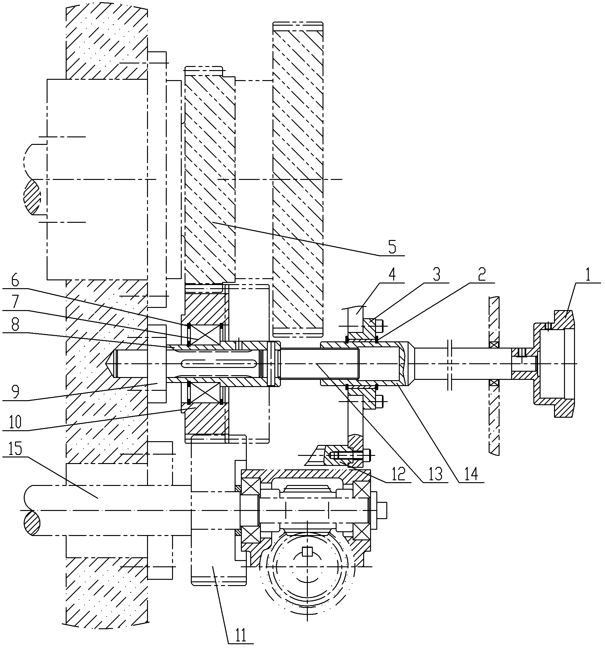
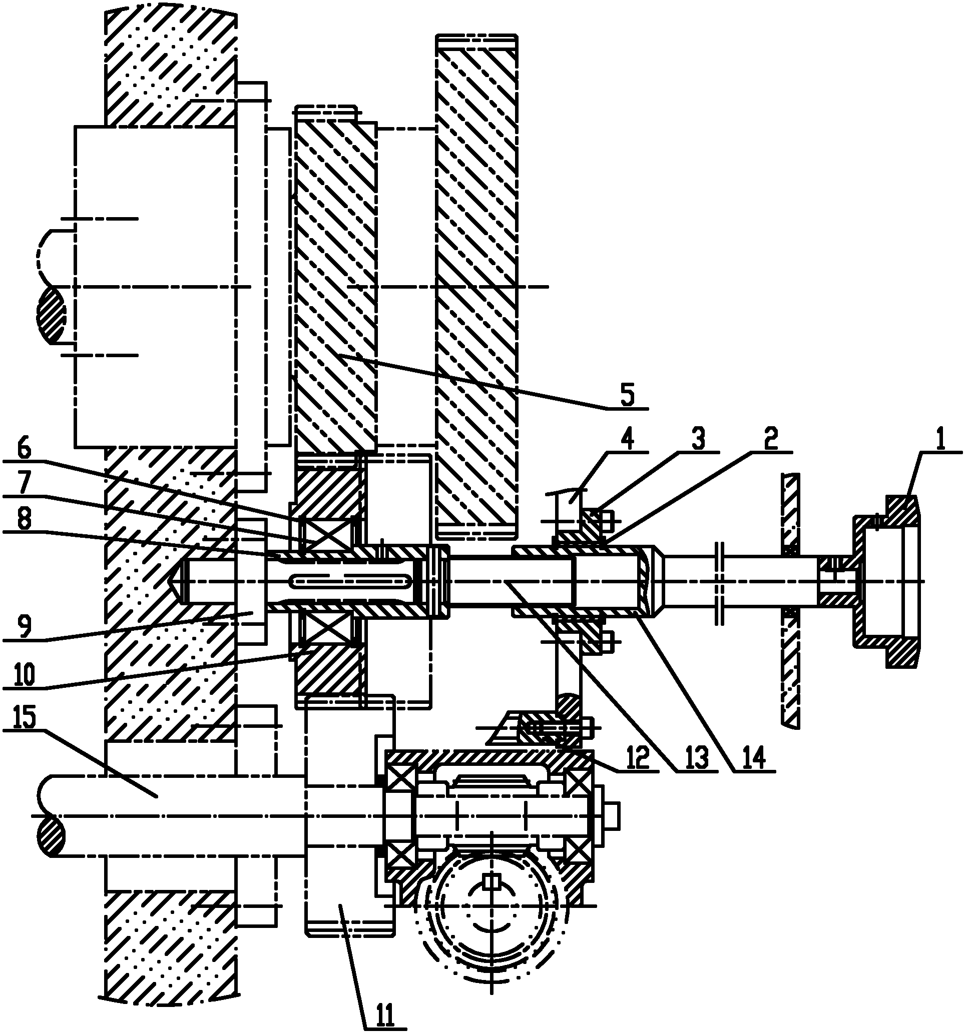
[0013] figure 1 Including hand wheel 1, oil seal 2, nut seat 3, support plate 4, plate roller gear 5, retaining ring 6, bearing 7, bearing seat 8, shaft 9, clutch gear 10, ink roller gear 11, and support rod 12 , Screw rod 13, nut 14, string ink roller 15 etc.

[0014] like figure 1 As shown, the present invention is an ink roller clutch device, which is arranged between the axis-parallel version roller gear 5 and the ink roller gear 11, and the ink roller gear 11 is installed on the ink roller 15. The present invention includes a clutch gear 10 that meshes with both the printing roller gear 5 and the stringer roller gear 11 . The clutch gear 10 is rotatably installed on the bearing seat 8 through the bearing 7, and the bearing seat 8 is slidably fitted on the shaft 9 through the spline fit, and the shaft 9 is installed on the wallboard o...


PUM


Abstract

The invention relates to an inking roller clutch device arranged between a printing roller gear and an ink distributing roller gear with parallel axial lines. The inking roller clutch device comprises a clutch gear engaged with the printing roller gear and the ink distributing roller gear, the clutch gear is rotatably installed on a bearing block, the bearing block is in sliding fit with a shaft,a screw rod is fixed on the bearing block, the screw rod is in threaded connection with a nut, the nut is rotatably installed in a nut seat, and a hand wheel is fixedly connected with the nut. According to the invention, a threaded transmission mechanism is operated manually to drive the clutch gear to axially move, thereby rotating and stopping the ink distributing roller gear, and the inking roller clutch device has a simple structure, reliable performance and low cost.

Description

technical field [0001] The invention relates to a printing machine, in particular to an ink roller clutch device for meshing and separating the plate roller gear and the string ink roller gear. Background technique [0002] When the inker roller works normally, its rotational power is provided by the roller gear, and a clutch device is arranged between the roller gear and the inker roller, and the clutch gear of the clutch device meshes with the roller gear and the inker roller gear respectively. The plate roller gear is transmitted to the clutch gear through gear engagement and then passed to the string ink roller gear on the string ink roller. The clutch device in the prior art is driven by a cylinder, has a complex structure, high cost, and often breaks down due to the influence of oil mist, resulting in unstable performance. Contents of the invention [0003] The present invention aims at the above problems and provides an ink roller clutch device with simple structur...

Claims


Application Information

Patent Timeline
Patent Type & Authority Applications(China)
IPC IPC(8): B41F31/30
Inventor 吕爱萍
Owner WUXI BAONAN MACHINE MFG
Learn More