
Four-roller direct-driving type diamond wire numerical control slicer

A technology of diamond wire and slicing machine, applied in stone processing equipment, working accessories, fine working devices, etc., can solve the problems of large space occupied by motors and transmission mechanisms, increasing uncertain factors, and affecting slicing processing, etc. The effect of small space, low production cost and high production efficiency

Inactive Publication Date: 2012-02-15
DALIAN LIANCHENG NUMERICAL CONTROL MACHINE
View PDF7 Cites 9 Cited by
  • Summary
  • Abstract
  • Description
  • Claims
  • Application Information

AI Technical Summary

Problems solved by technology

The slicer with this structure has the following disadvantages: the motor and the transmission mechanism take up a lot of space, and the structure is complicated; the feeding of the upper and lower workpieces (silicon rods) is one of pressing wire cutting and the other of drawing wire cutting. This processing method, as follows The quality of silicon wafers processed by pull processing is not high, with obvious chip marks, and the quality level of the chips is lower than that of press processing. Moreover, once a wire breaks in this winding method, it will affect the entire slicing process.
Therefore, only by effectively controlling the tension of the steel wire can the processing quality of silicon wafers be improved, and the method of using ordinary steel wire and silicon carbide mortar not only has low processing efficiency, but also the processing efficiency and the quality of the slice are affected by the temperature and flow rate of the mortar. , density, silicon carbide particle size and shape and other factors, which increase the uncertain factors in the processing process, it is difficult to comprehensively and effectively control
These are the deficiencies of general slicers, and the processing efficiency is low

Method used

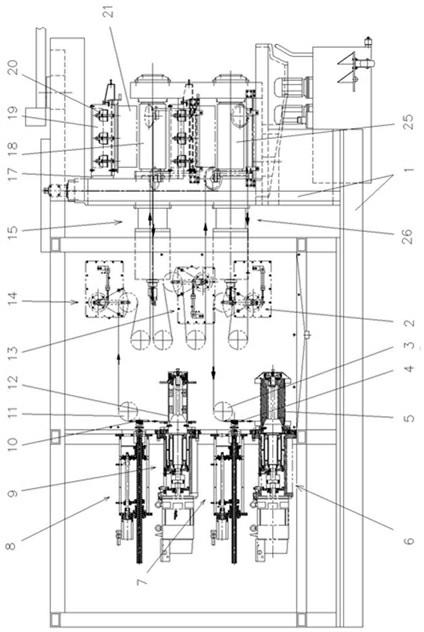
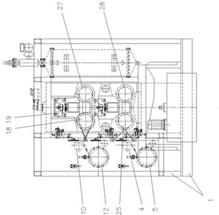
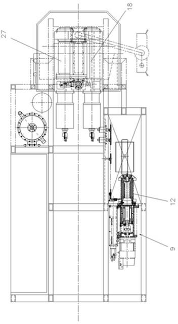

Image

  • Four-roller direct-driving type diamond wire numerical control slicer
  • Four-roller direct-driving type diamond wire numerical control slicer
  • Four-roller direct-driving type diamond wire numerical control slicer

Examples


Embodiment Construction

[0023] Such as figure 1 , 2 , shown in 3: 1 is a frame, and frame 1 adopts section steel welding to manufacture, and four groups of cutting roller mechanisms that the axes of upper, lower, left and right distributions are arranged parallel to each other are installed on frame 1, and 15 is upper left cutting Roller mechanism, 26 is the lower left cutting roller mechanism. The right part of upper left cutting roller mechanism 15 is equipped with upper left cutting roller 18, and the right part of lower left cutting roller mechanism 26 is equipped with lower left cutting roller 25. The upper right cutting roller 27 is equipped with on the right part of the upper cutting roller mechanism on the right side, and the lower right cutting roller 28 is equipped with on the right part of the lower cutting roller mechanism.

[0024] The upper take-up and pay-off mechanism 9 and the last take-up and pay-off follow-up mechanism 8 are installed on the frame 1, and the upper take-up and tak...


PUM

PropertyMeasurementUnit
thicknessaaaaaaaaaa

Abstract

The invention discloses a four-roller direct-driving type diamond wire numerical control slicer, which is characterized in that four groups of cutting roller mechanisms and two groups of wire retracting and following mechanisms are arranged on a machine frame, and tension control mechanisms are arranged between the wire retracting mechanisms and the cutting roller mechanisms. Clamping mechanisms which are driven by a lifting mechanism are arranged on the machine frame; cutting wires are wound on each wire retracting wheel in each of the wire retracting mechanisms and on each cutting roller ineach of the cutting roller mechanisms; the cutting roller mechanism is in a direct-driving type; the cutting rollers in the two upper groups of cutting roller mechanisms and the cutting rollers in the two lower groups of cutting roller mechanisms are respectively and pairwise wound by the cutting wires; an intermediate tension control mechanism is arranged on the machine frame; the cutting wires are wound on the intermediate tension control mechanism between the upper and lower cutting roller mechanisms; and the cutting wires are diamond wires. The four-roller direct-driving type diamond wirenumerical control slicer has a simplified structure, a small occupation space, good cutting quality, high precision and uniform tension control; the clamping mechanisms are flexible and reliable whenmoving up and down; a work-piece clamp is firm and convenient, and has a simple structure and a large clamping force; and the four-roller direct-driving type diamond wire numerical control slicer also has high production efficiency, low defective rate and low production cost.

Description

technical field [0001] The invention relates to a slicer, in particular to a four-roller direct-drive diamond wire numerical control slicer for cutting silicon material into sheets. Background technique [0002] At present, the structure of the slicing machine for cutting silicon materials into sheet materials is as follows: it includes a frame, and four groups of cutting roller mechanisms arranged in parallel to each other are installed on the frame. The upper take-up and pay-off mechanism and the upper take-up and take-off follow-up mechanism matched with the upper two sets of cutting roller mechanisms, and the lower take-up and take-off mechanism and the lower take-up and take-off follower mechanism that cooperate with the lower two sets of cutting roller mechanisms are also installed on the frame ; An upper tension control mechanism is provided between the upper take-up and release line follower mechanism and the upper cutting roller mechanism, and a lower tension contro...

Claims


Application Information

Patent Timeline
Patent Type & Authority Applications(China)
IPC IPC(8): B28D5/04B28D7/04
Inventor 张树礼樊治平林国光王钢
Owner DALIAN LIANCHENG NUMERICAL CONTROL MACHINE
Learn More