
Pesticide spraying plant protection machine

A mechanical and plant protection technology, which is applied to the device, application, and animal husbandry of catching or killing insects, and can solve the problems of loud noise, single function, waste of power and energy, etc.

Inactive Publication Date: 2012-02-15
庄如强
View PDF8 Cites 9 Cited by
  • Summary
  • Abstract
  • Description
  • Claims
  • Application Information

AI Technical Summary

Problems solved by technology

Disadvantages: The car engine and the sprayer engine work at the same time, which wastes power and energy
Disadvantages: agricultural vehicle engine and sprayer engine work at the same time, waste of power and energy
Disadvantages: It can only be sprayed downwards, it can only be used on flat land, it cannot be used for tall crops, and it cannot be used in mountains and hills
Disadvantages: slow human walking speed; high temperature, loud noise, fast diffusion of smoke, great harm to human body
The above spraying plant protection machines not only have their own defects, but also have single functions and low efficiency.

Method used


Image

  • Pesticide spraying plant protection machine
  • Pesticide spraying plant protection machine
  • Pesticide spraying plant protection machine

Examples


Embodiment Construction

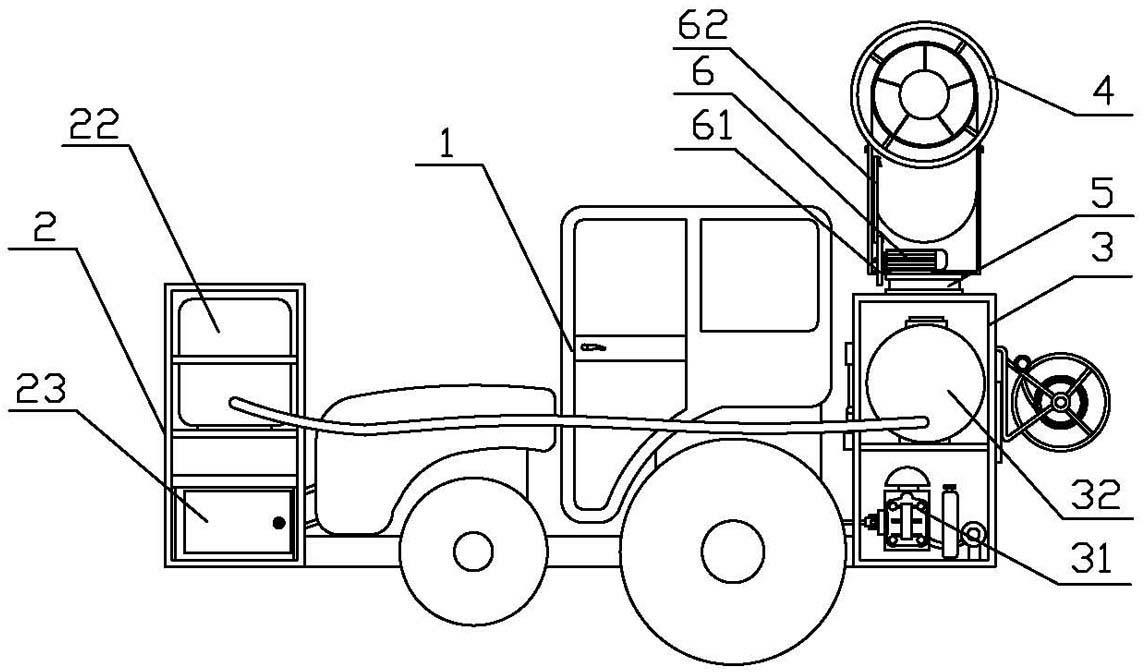
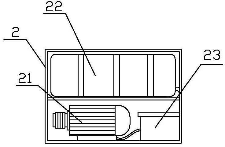
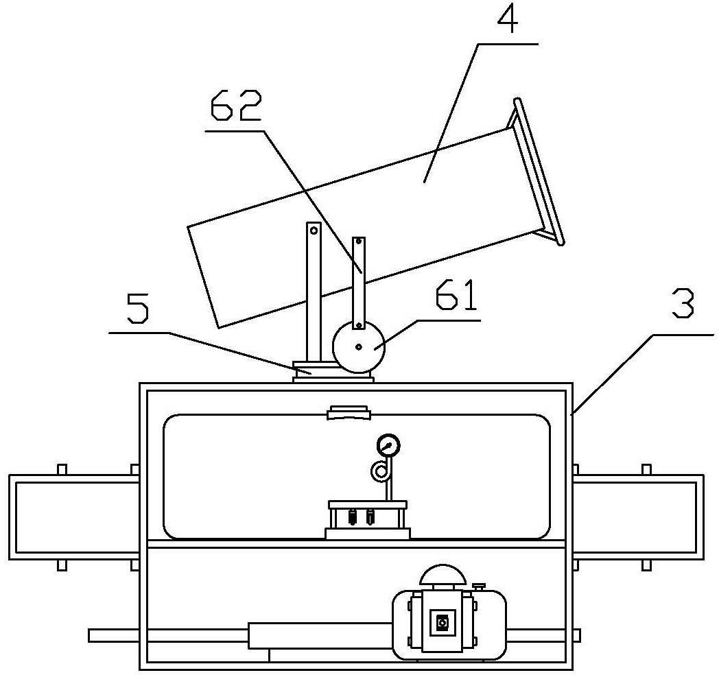
[0015] Such as figure 1 As shown, a kind of pesticide spraying plant protection machinery of the present invention comprises tractor 1, the front support 2 that is installed in tractor 1 front end, the rear support 3 that is installed in tractor 1 rear end, front support 2 and rear support 3 all are square steel, A rectangular frame structure welded by angle iron or channel steel, used to support and install other components. Such as figure 2 As shown, a generator 21 and a counterweight medicine box 22 are installed on the front bracket 2, the generator 21 is connected to the flywheel of the tractor, and the power output terminal of the generator 21 is electrically connected to the distribution box 23, and the distribution box 23 is also installed on the front support 2 and is located on one side of the generator 21; as image 3 , Figure 4 As shown, a diaphragm pump 31 and a main drug box 32 are installed on the rear support 3, the diaphragm pump 31 is connected to the re...


PUM


Abstract

The invention relates to an agricultural machine, in particular to a pesticide spraying plant protection machine. The pesticide spraying plant protection machine comprises a tractor, a front bracket arranged at the front end of the tractor and a rear bracket arranged at the rear end of the tractor. The pesticide spraying plant protection machine is characterized in that: a generator and a counterweight pesticide tank are arranged in the front bracket, the generator is in transmission connection with a flywheel of the tractor, and the power supply output end of the generator is electrically connected with a distribution box; a diaphragm pump and a main pesticide tank are arranged in the rear bracket, the diaphragm pump is in transmission connection with a rear power output shaft of the tractor through a coupling, the main pesticide tank is communicated with the counterweight pesticide tank through a duct, the input end of the diaphragm pump is communicated with the main pesticide tank through a duct, and the output end of the diaphragm pump is connected with a spraying device through a distributor; the pesticide spraying plant protection machine integrates the functions of four sprayers into a whole; and by adopting an engine of the tractor as power, the utilization rate of the power is improved, energy consumption is reduced, and discharge is reduced. Meanwhile, the pesticide spraying plant protection machine has the characteristics of small turning radius, strong flexibility and low requirement for road conditions. The pesticide spraying plant protection machine is suitable for plains, mountain lands and hills, suitable for short-stem crops and high-stem crops and suitable for field crops, orchards and nurseries, and can also be applied in the fields of gardening, municipal disinfection, disease and insect pest prevention and control of forests, epidemic prevention, environment friendliness and dust removal and the like.

Description

technical field [0001] The invention relates to an agricultural machine, in particular to a plant protection machine for spraying pesticides. technical background [0002] Existing spraying plant protection machinery is mainly divided into four categories: 1. Vehicle-mounted air-driven sprayer: a light truck is used as the driving force, and the rear-loaded air-driven sprayer is equipped with a diesel generator set on the sprayer. Disadvantages: The car engine and the sprayer engine work at the same time, which wastes power and energy. The car has a large turning radius and has high requirements on road conditions, so it is not suitable for field operations. 2. Stretcher-type sprayer: The agricultural vehicle is used as the driving force, the gasoline engine drives the high-pressure pump, and the operator holds the spray gun to work. Disadvantages: The engine of the agricultural vehicle and the engine of the sprayer work at the same time, which wastes power and energy. 3....

Claims


Application Information

Patent Timeline
Patent Type & Authority Applications(China)
IPC IPC(8): A01M7/00
Inventor 庄如强
Owner 庄如强
Learn More