
Gas-water separation, water discharging and slag discharge integrated device for drill hole in gas extraction crossheading drill site

A technology of gas drainage and gas-water separator, which is applied in the direction of gas discharge, safety devices, separation methods, etc. It can solve the problems of inconvenient use on site, affecting the effect of drainage, and small water release, and achieves convenient maintenance and on-site use , good water discharge effect and increased water release effect

Inactive Publication Date: 2012-02-01
山东新矿赵官能源有限责任公司
View PDF7 Cites 13 Cited by
  • Summary
  • Abstract
  • Description
  • Claims
  • Application Information

AI Technical Summary

Problems solved by technology

Within the construction height of the designed borehole, if there is an aquifer or there is water in the borehole due to cracks, when the borehole comes out of water, the gas drainage pipeline is easily blocked by water, causing the pipeline to be blocked or even blocked, affecting Drain effect
In order to overcome this problem, the existing technology is to use the negative pressure automatic water release device of the gas drainage pipeline, but the water discharge effect is not ideal. Blockage, large amount of maintenance, extremely inconvenient to use on site

Method used


Image

  • Gas-water separation, water discharging and slag discharge integrated device for drill hole in gas extraction crossheading drill site
  • Gas-water separation, water discharging and slag discharge integrated device for drill hole in gas extraction crossheading drill site
  • Gas-water separation, water discharging and slag discharge integrated device for drill hole in gas extraction crossheading drill site

Examples


Embodiment 1

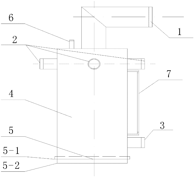
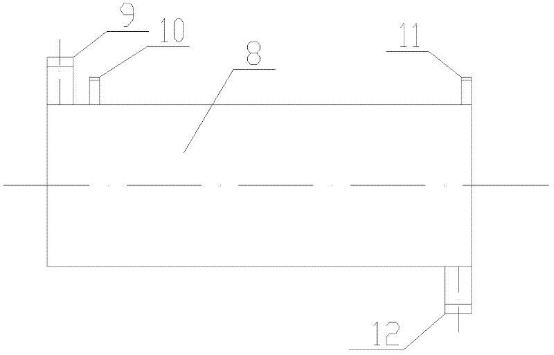
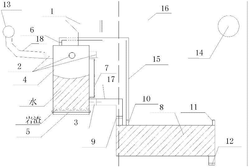
[0028] An integrated gas-water separator, water discharge and slag discharge integrated device for gas drainage drilling site, including gas-water separator and water discharge device, the structure is as follows Figure 1-4 shown.

[0029] The tank body 4 of the gas-water separator is a Φ273mm steel cylindrical container with a height of 0.6m. On the wall of the container, there are 4 drill holes connected to the nozzles 2 in a circular, symmetrical and equidistant manner. The 4 drilled holes connected to the nozzles 2 are all For the Φ50mm nozzle with valve, the 4 drill holes connect the nozzle 2 with the drill hole 13 in the drill field along the groove through the rubber hose 18 with a steel wire skeleton in the pipe wall, and the 4 drill holes can be Simultaneously communicate with respectively 4 boreholes in the drill field along the groove, also can only connect the borehole 13 in the drill field along the groove as required (such as image 3 shown), or connect 3 boreho...


PUM


Abstract

The invention relates to a gas-water separation, water discharging and slag discharging integrated device for a drill hole in a gas extraction crossheading drill site. The device comprises a gas-water separator and a water discharger, wherein a pipe orifice respectively communicated with the drill hole and a gas extraction pipe in the crossheading drill site is formed on the gas-water separator; the lower part of a container is provided with a water discharge hole; the bottom part of the container is provided with a slag discharge hole; a liquid level observation pipe is arranged out of the container; a water inlet and a gas outlet valve are formed on the top part at one end of the water discharger; a gas inlet valve is arranged on the top part at the other end of the water discharger; and a water discharge valve is arranged on the bottom part of the water discharger. By using the gas-water separation, water discharging and slag discharging integrated device for the drill hole in the gas extraction crossheading drill site provided by the invention, gas-water separation is implemented at the drill hole and then the water is discharged through the water discharger, so that reduction in extraction effect caused by a reason that an extraction pipeline is blocked by water or extraction resistance is increased due to water in the pipeline can be prevented. The device has a simple structure and a good water discharging effect.

Description

technical field [0001] The invention relates to a gas drainage and slag discharge device, in particular to an integrated device for gas-water separation, water discharge and slag discharge in a gas drainage drilling site. Background technique [0002] At present, in high-gas mines or gas-focused areas, drilling is carried out in down-channel drilling sites, and gas drainage is carried out through drilling to achieve the purpose of gas control or gas utilization. Within the construction height of the designed borehole, if there is an aquifer or there is water in the borehole due to cracks, when the borehole comes out of water, the gas drainage pipeline is likely to be blocked by water, causing the pipeline to be blocked or even blocked. Draw effect. In order to overcome this problem, the existing technology is to use the negative pressure automatic water release device of the gas drainage pipeline, but the water discharge effect is not ideal. Blockage, large amount of maint...

Claims


Application Information

Patent Timeline
IPC IPC(8): E21F7/00E21F16/00B01D19/00
Inventor 何希霖刘永禄孙通张胜文王旺旺李云志
Owner 山东新矿赵官能源有限责任公司
Learn More