
Novel multiaxis machining machine

A multi-axis machining and mechanical technology, applied in metal processing machinery parts, metal processing equipment, manufacturing tools, etc., can solve problems such as affecting the balance of feed movements and machining accuracy, high requirements for processing machinery structures, and unreasonable structural configuration. , to achieve the effect of reducing volume and weight, improving service life and good bearing capacity

Inactive Publication Date: 2012-01-25
四川欧曼机械有限公司
View PDF9 Cites 12 Cited by
  • Summary
  • Abstract
  • Description
  • Claims
  • Application Information

AI Technical Summary

Problems solved by technology

[0004] However, the unreasonable structural configuration of the linear motors in the existing processing machines is likely to affect the balance and machining accuracy of the feed action. The structure requirements of processing machinery are relatively high. The current processing machinery base is not designed for linear motors, which is prone to structural deformation, resulting in transmission failure and reduced accuracy.

Method used


Image

  • Novel multiaxis machining machine
  • Novel multiaxis machining machine
  • Novel multiaxis machining machine

Examples


Embodiment Construction

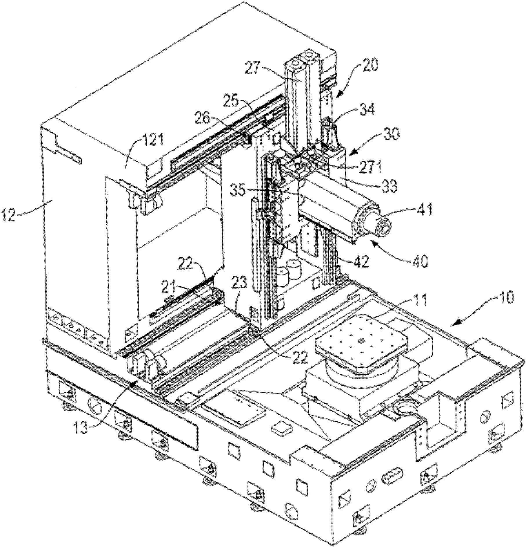
[0025] see figure 1 , shows a schematic perspective view of the novel multi-axis processing machine of the present invention.

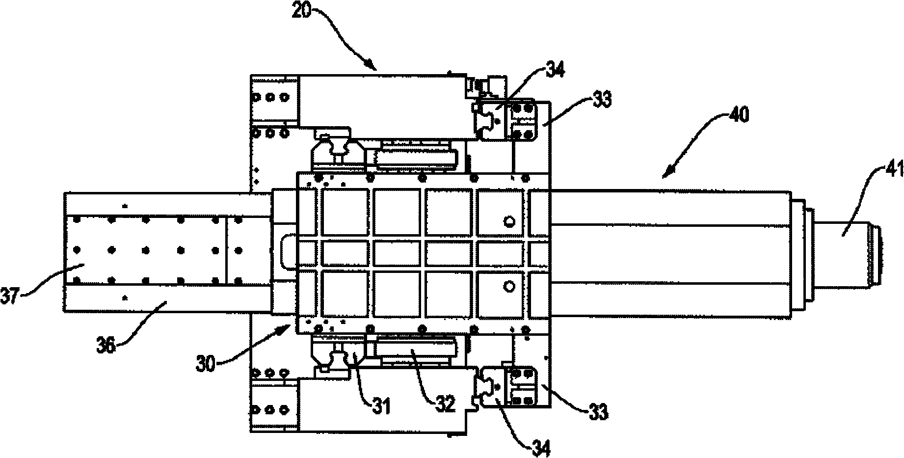
[0026] The processing machine includes a base 10 , a vertical table 20 , a tool head box 30 and a spindle head seat 40 .

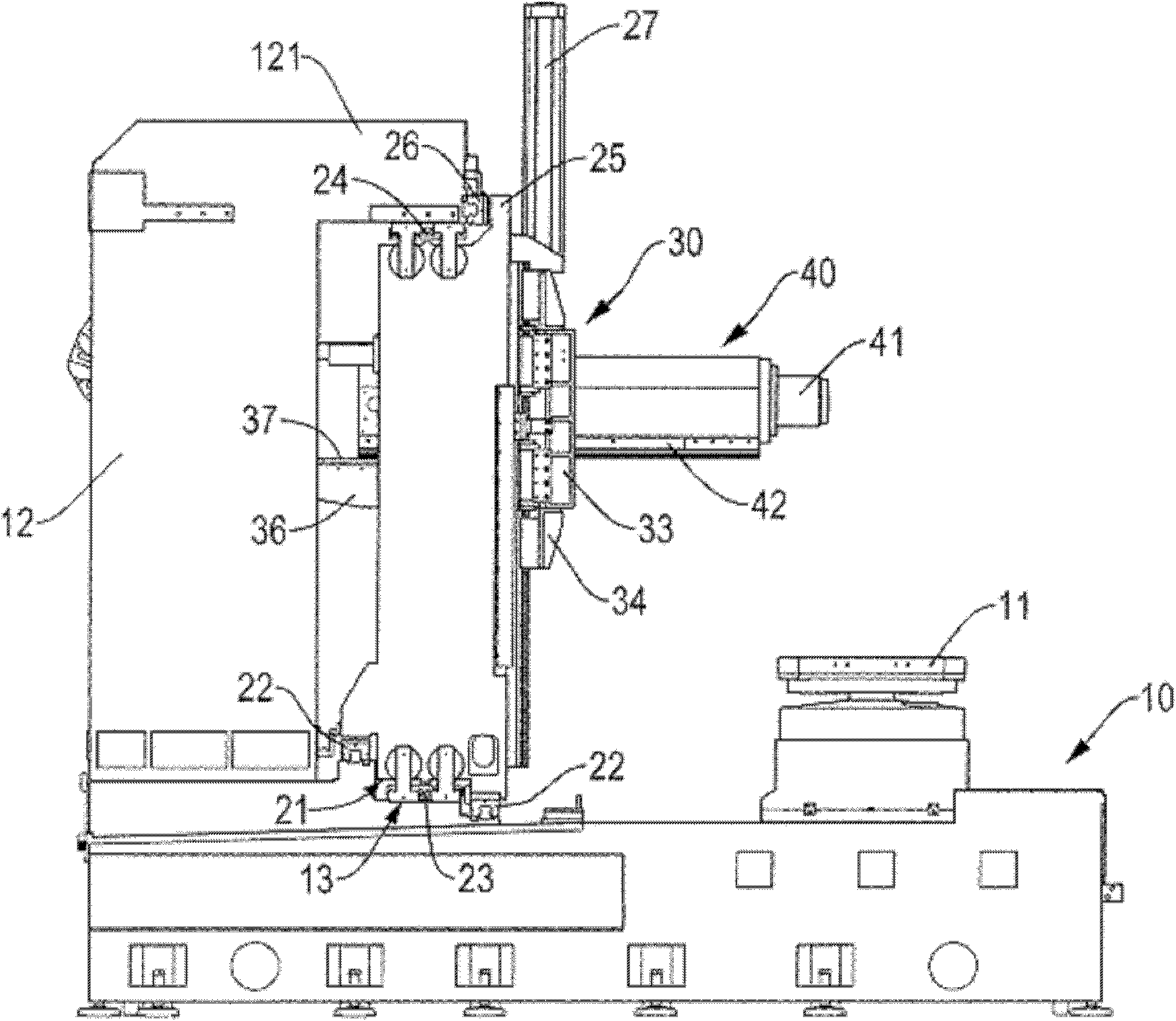
[0027] Among them, see also figure 2 One side of the base 10 is provided with a workbench 11, the workpiece can be placed on the workbench 11 during processing, and the other side of the base 10 is provided with an upright base 12, the base 12 is a square frame with an inner space, The top end of the base 12 extends toward the direction of the workbench 11 to a joint part 121 , below the joint part 121 , the base 10 is provided with three steps 13 , and the three steps 13 climb up from the workbench 11 to the base 12 sequentially.

[0028] Wherein, the vertical platform 20 is a square frame body, and the bottom of the vertical platform 20 corresponds to the three-layer step portion 13 on the base 10 to form a corresponding comb...


PUM


Abstract

The invention relates to a novel multiaxis machining machine which comprises a chassis, a vertical type stand, a cutter bit box and a spindle head seat, wherein a workbench for bearing a workpiece is arranged at one side of the chassis, and an erectly arranged base which is a square framework with an inner space is arranged at the other side of the chassis; a combined part is extended from the top end of the base to the direction of the workbench; the chassis is provided with a three-layer step part under the combined part; the three-layer step part sequentially climbs upwards from the workbench to the base; the vertical type stand is a square framework body; a corresponding combined step is formed on a position at the bottom of the vertical type stand, corresponding to the three-layer step part on the chassis; first horizontal linear guides are respectively arranged between the front end of the combined step and the rear end of the combined step as well as between the first step of the three-layer step part and the third step of the three-layer step part; one first linear guide is set to be high, and the other first linear guide is set to be low; and a first horizontal linear electric motor is arranged between the middle end of the combined step and the second step of the three-layer step part, therefore, a first horizontal feeding mechanism is formed between the vertical type stand and the three-layer step part of the chassis.

Description

technical field [0001] The invention relates to the field of cutting machines, in particular to a novel multi-axis machining machine with improved stability and machining accuracy. Background technique [0002] Most of the existing multi-axis processing machines are three-axis or five-axis processing machines, and ball guide rods or screws are generally used for multi-axis feeding. However, such feeding accuracy and speed are low, and cannot adapt to the current stage of increasingly high processing requirements. [0003] In order to overcome the defects of ball guide rods or screws, linear motors are more and more widely used in the feed control of processing machinery. The servo response and dynamic cutting rigidity of linear motors are relatively high, and the feed accuracy is much higher than that of ball guides. The feed of the rod or screw adopts a modular design, with fewer parts and very convenient maintenance. [0004] However, the unreasonable structural configur...

Claims


Application Information

Patent Timeline
IPC IPC(8): B23Q5/34B23Q1/01
Inventor 李梁
Owner 四川欧曼机械有限公司
Learn More