Light-emitting measuring device, light-emitting measuring method, control program and readable recording medium

A technology for measuring device and luminescence state, which is applied in the field of luminescence measurement device, luminescence measurement, control program and readable recording medium, which can solve problems such as poor dust adhesion and inability to check the directivity of LED light emission, and achieve the effect of easy directivity

Inactive Publication Date: 2014-12-24
SHARP KK
View PDF7 Cites 0 Cited by
  • Summary
  • Abstract
  • Description
  • Claims
  • Application Information

AI Technical Summary

Problems solved by technology

[0038] Regardless of the type, in the above-mentioned conventional luminescence measurement devices 100 and 200, the LED and the light-receiving diode PD are arranged opposite to each other in a one-to-one manner, and the luminescence amount of the LED is converted into a power measurement by the photodiode PD. The amount of light emitted by LEDs, however, has the problem that it is only possible to measure whether the amount of light emitted by LEDs has reached a reference value, and it is impossible to check the directivity of LED light emission, poor adhesion of dust, etc.

Method used


Image

  • Light-emitting measuring device, light-emitting measuring method, control program and readable recording medium
  • Light-emitting measuring device, light-emitting measuring method, control program and readable recording medium
  • Light-emitting measuring device, light-emitting measuring method, control program and readable recording medium

Examples


Embodiment approach 1

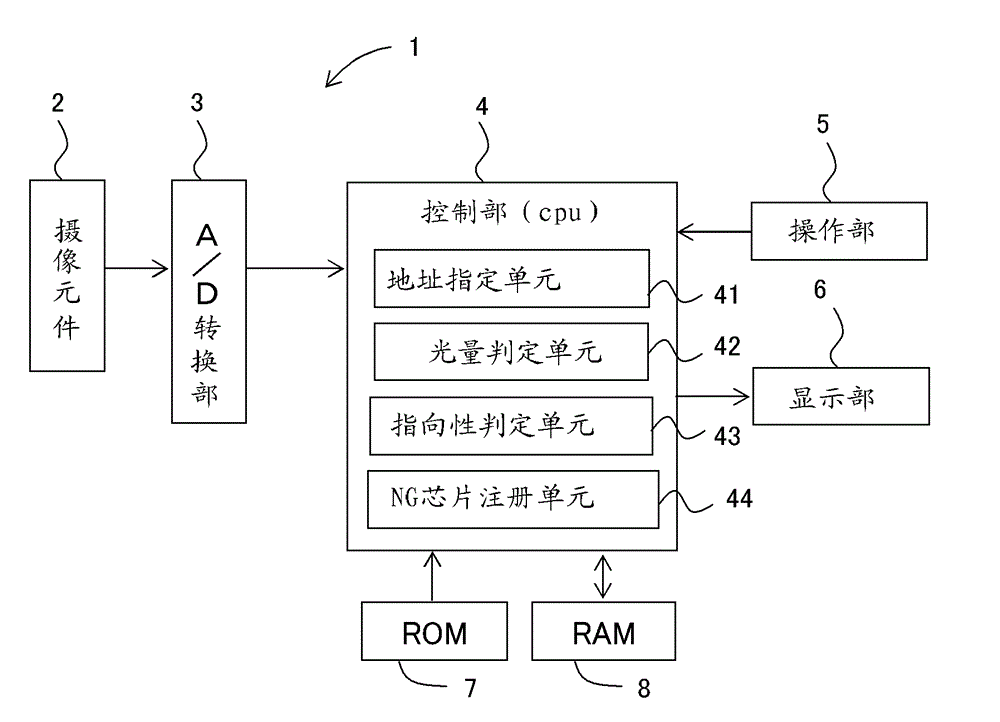
[0102] figure 1 It is a block diagram showing a configuration example of main parts of the luminescence measurement device in Embodiment 1 of the present invention.

[0103] figure 1 Among them, the luminescence measurement device 1 according to Embodiment 1 has a plurality of light sources that photoelectrically convert incident light from a subject and capture images when LEDs that are light-emitting elements of the semiconductor chip 12 described later are made to emit light. The receiving unit is arranged in a matrix-like imaging element 2; the A / D conversion unit 3 that performs A / D conversion after removing noise from the imaging signal from the imaging element 2; the CPU (central processing unit) that performs overall control and luminescence measurement control A control unit 4 composed of a processing device); an operation unit 5 such as an input device for receiving input through a keyboard, a mouse, a touch screen, and a pen input device for inputting instruction...


PUM


Abstract

The invention relates to a light-emitting measuring device and a light-emitting measuring method, a program and a medium, capable of not only measuring the light-emitting amount of an optical element easily and accurately, measuring the light-emitting amounts of a plurality of optical elements easily and accurately without using a conventional ID identification circuit, but also measuring the light-emitting directivities and dust attachment badness of the optical elements easily and accurately. The light-emitting measuring method comprises the steps of using an address designating unit(41) to carry out address designation on a or a plurality of optical receiving parts among a plurality of optical receiving parts at light-emitting states of a camera LED; using a light-emitting amount judging unit(42) to compare a camera signal value with a reference value come from the or the plurality of optical receiving parts designated by the address designating unit(41) and judge the light-emitting amount, when the camera signal value is less than the reference value, the light-emitting amount is judged to be bad, and when the camera signal value is greater than the reference value, the light-emitting amount is judged to be good; using a directivity judging unit(43) to judge whether the directivity of the LED light-emitting is good or not by comparing the camera signal value with the reference value come from the or the plurality of optical receiving parts designated by the address designating unit(41).

Description

technical field [0001] The present invention relates to a luminescence measurement device and a luminescence measurement method for inspecting luminescence of optical elements such as light-emitting diodes (hereinafter referred to as LEDs), a control program for causing a computer to execute the luminescence measurement method, and a readable recording medium storing the control program. Background technique [0002] In recent years, from the viewpoint of global environmental protection, the demand for low-cost LEDs has been very high as the necessity of LEDs has been recognized as energy-saving lighting components that are small in size, long in life, and free of harmful substances. [0003] In conventional LED measurement, LEDs and photodiodes (photodiodes) are arranged one-to-one to face each other (opposite), and each light-receiving sensor converts light into electricity to measure the amount of light emitted by the LED. This is because, in the case of simultaneously em...

Claims


Application Information

Patent Timeline
Patent Type & Authority Patents(China)
IPC IPC(8): G01R31/26
CPCG01J1/08G01J1/14G01J1/124H04N25/68
Inventor 斎藤仁尾上毅
Owner SHARP KK
Why Eureka
Try Eureka