
Method and apparatus for determining discharge flow rate and use of the apparatus

a flow rate and flow rate technology, applied in the direction of liquid/fluent solid measurement, machines/engines, instruments, etc., can solve the problems of inability to be readily moved, stop the fluid transport, and significant pressure loss of transported fluid, so as to achieve accurate and easy the effect of achieving and realizing even more easily and effectively

Active Publication Date: 2013-03-12
TLV CO LTD
View PDF13 Cites 0 Cited by
  • Summary
  • Abstract
  • Description
  • Claims
  • Application Information

AI Technical Summary

Benefits of technology

The patent describes a method for determining the flow rate of a fluid discharged from a device. This method uses sonic waves to measure the distance between the device and a nearby site, which is then used to calculate the flow rate of the fluid. The method is versatile and can be easily adapted to different distances between the device and the site. This allows for easy determination of the fluid flow rate, even when the distance between the device and the site changes. The method can be used with different types of instruments and can be determined through visual inspection or estimation. Overall, the method provides a fast and accurate way to determine the flow rate of fluids from devices.

Problems solved by technology

These known flowmeters suffer the problem that the flowmeter when incorporated acts as a passageway resistance, thus resulting in significant pressure loss of the transported fluid.
Another problem thereof is the need to stop the fluid transport in order to incorporate the flowmeter in an existing pipe passageway.
They suffer a still further problem of inability to be readily moved to a site where a flow rate determination is needed.
With this too, an apparatus or the like needs to be mounted to a pipe passageway, so there is the problem of its mounting requiring significant trouble.
In particular, if the site to be determined is located at a hardly accessible location such as a high site, the mounting operation requires great trouble and mounting cost.

Method used


Image

  • Method and apparatus for determining discharge flow rate and use of the apparatus
  • Method and apparatus for determining discharge flow rate and use of the apparatus
  • Method and apparatus for determining discharge flow rate and use of the apparatus

Examples


Embodiment Construction

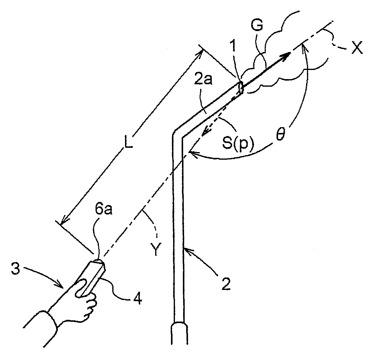
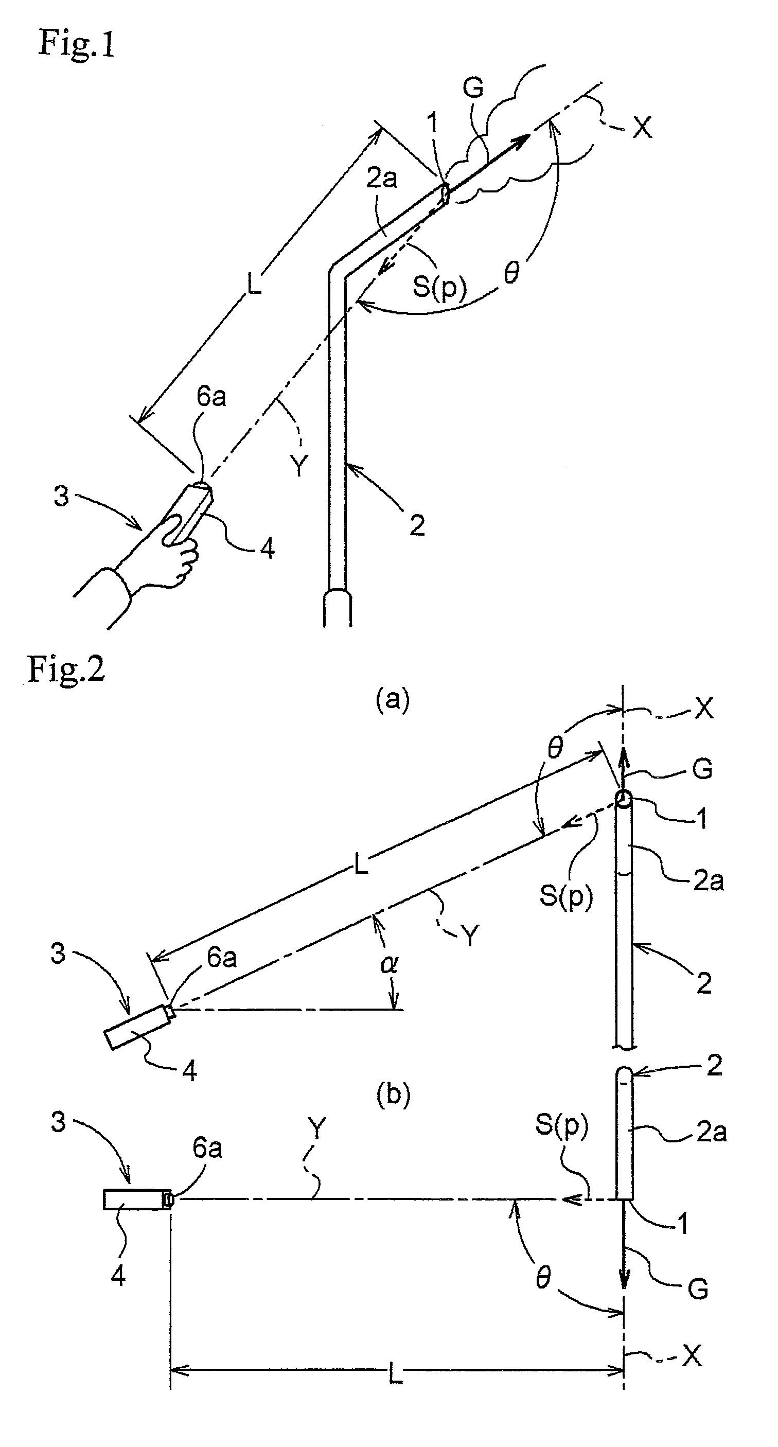
[0117]FIG. 1 shows a condition in which a discharge flow rate Q of a gas G (e.g. factory exhaust gas to be discharged into the atmosphere) discharged from a discharge opening 1 provided outdoors is being determined. The discharge opening 1 is formed at the leading end of a discharge pipe 2 (discharge passageway) installed vertically.

[0118]In order to prevent entrance of raindrops or water into the discharge pipe 2, an upper end portion 2a of the discharge pipe 2 is bent oblique. The discharge opening 1 is formed by cutting off the leading end of the discharge pipe upper end portion 2a along a pipe axis X such that its opening face may assume a substantially perpendicular posture and oriented toward the bending direction of the leading end of the discharge pipe upper end portion 2a.

[0119]As the discharge opening 1 is located at a high position, determination of the discharge flow rate Q will be effected as the user looks up the discharge opening 1 as illustrated in FIG. 2 (a). In th...


PUM


Abstract

The object is to facilitate determination of a flow rate of fluid discharged from a discharge opening.Intensity of a supersonic wave generated at and propagated from a discharge opening in association with discharge of the fluid from the discharge opening is determined at a determinate site distant from the discharge opening. And, a propagation distance from the discharge opening to the determination site is determined or investigated. Then, based upon a correlation existent among the intensity of the propagated supersonic wave, the propagation distance and the fluid discharge flow rate from the discharge opening, the fluid discharge rate is obtained from the determined or investigated supersonic wave intensity and the propagation distance.

Description

TECHNICAL FIELD[0001]The present invention relates to a method and an apparatus for determining a discharge flow rate of fluid discharged from a discharge opening formed at a terminal end of a discharge passageway installed in a factory or the like that discharges or emits various kinds of fluid. The invention relates also to use of such discharge flow rate determining apparatus.BACKGROUND ART[0002]As flowmeters, various types are known. Many of them are configured to be incorporated in midway a pipe passageway (see Patent Document 1). These known flowmeters suffer the problem that the flowmeter when incorporated acts as a passageway resistance, thus resulting in significant pressure loss of the transported fluid. Another problem thereof is the need to stop the fluid transport in order to incorporate the flowmeter in an existing pipe passageway. They suffer a still further problem of inability to be readily moved to a site where a flow rate determination is needed.[0003]Further, som...

Claims


Application Information

Patent Timeline
Patent Type & Authority Patents(United States)
IPC IPC(8): G01F1/66G06F19/00G01M3/24
CPCG01F1/66G01M3/24G01N29/14G01P5/24G01N2291/021G01N2291/02836
Inventor YONEMURA, MASAO
Owner TLV CO LTD
Learn More