Radiator, electronic apparatus and installation method thereof
A radiator and printed circuit board technology, applied in circuits, electrical components, electrical solid devices, etc., can solve the problem that technical indicators cannot be taken into account, and achieve good technical effects, good thermal conductivity, and easy disassembly of the radiator.
- Summary
- Abstract
- Description
- Claims
- Application Information
AI Technical Summary
Problems solved by technology
Method used
Image
Examples
Embodiment 1
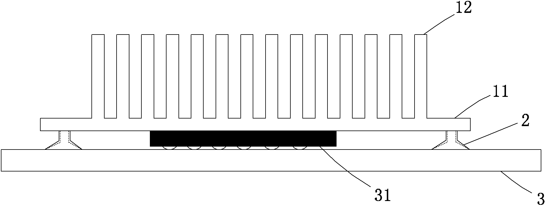
[0024] like figure 1 As shown, the heat sink provided by the embodiment of the present invention includes a base and fins, the base is provided with a suction cup, and the suction cup is used to adsorb the heat sink to the printed circuit board by air pressure. The base 1 is usually rectangular, so as a preferred solution, the suction cups 2 are arranged on the four corners of the base 1, of course, the number and positions of the suction cups can also be changed according to the actual situation.
[0025] The installation method of the radiator provided by the embodiment of the present invention is:
[0026] Press the suction cup 2 on the radiator against the printed circuit board 3 .
[0027] Use suction cup 2 to fix the radiator on PCB3, the base 1 can be in direct contact with IC31, and the heat conduction effect is good; the suction cup 2 is only adsorbed on the surface of PCB3, which does not affect the layout and wiring of PCB3, and will not generate single-board stres...
Embodiment 2
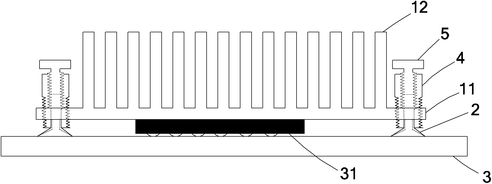
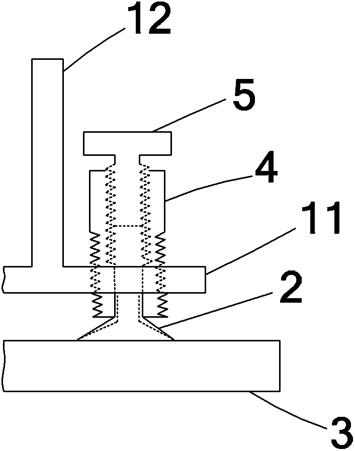
[0030] like figure 2 and image 3 As shown, in this embodiment, the pressure regulating component is a pressure regulating screw 5;
[0031] The installation method of the radiator provided by the embodiment of the present invention is:
[0032] Press the suction cup 2 on the radiator against the printed circuit board 3;
[0033] Rotate the pressure adjusting screw 5 to increase the volume of the gas in the sealed tube 4 .
[0034] After the suction cup 2 is pressed on the PCB3, a closed cavity is formed between the PCB3, the suction cup 2, the sealing tube 4 and the pressure regulating screw 5, and the volume of the closed cavity can be increased by rotating the pressure regulating screw 5, and the pressure of the gas inside can be increased. will decrease.
[0035] Because the pressure is inversely proportional to the volume, ignoring the internal volume of the suction cup, the cross-sectional area of the airtight chamber and the sealed tube is equal and constant, so ...
Embodiment 3
[0041] This embodiment is basically the same as Embodiment 2, the difference is that, as Figure 4 and Figure 5 As shown, in this embodiment, a height adjustment nut 6 is also included; the outer side of the sealing tube 4 is threaded, and the height adjusting nut 6 is screwed to the outer side of the sealing tube 4 for pressing against the base 11 .
[0042] The installation method of the radiator provided by the embodiment of the present invention is:
[0043] Press the suction cup 2 on the radiator against the printed circuit board 3;
[0044] Rotate the pressure regulating screw 5 to increase the volume of the gas in the sealed tube 4;
[0045] Rotate the height adjustment nut 6 to make the base 11 close to the integrated circuit 31 on the printed circuit board 3 .
[0046]After rotating the pressure adjusting screw 6, the suction cup 2 and the sealing tube 4 have been fixed on the PCB3. At this time, the height adjusting nut 6 can be rotated to lower the height of the...
PUM
 Abstract
Description
Claims
Application Information
 - R&D
- Intellectual Property
- Life Sciences
- Materials
- Tech Scout
- Unparalleled Data Quality
- Higher Quality Content
- 60% Fewer Hallucinations
Browse by: Latest US Patents, China's latest patents, Technical Efficacy Thesaurus, Application Domain, Technology Topic, Popular Technical Reports.
© 2025 PatSnap. All rights reserved.Legal|Privacy policy|Modern Slavery Act Transparency Statement|Sitemap|About US| Contact US: help@patsnap.com


