Channel allocation method, channel decorrelation method and DWDM (dense wavelength division multiplexing) transmission experimental system
An experimental system and de-correlation technology, applied in transmission monitoring/testing/fault measurement systems, wavelength division multiplexing systems, etc., can solve problems such as inability to correctly estimate the influence of cross-phase modulation
- Summary
- Abstract
- Description
- Claims
- Application Information
AI Technical Summary
Problems solved by technology
Method used
Image

Examples
no. 1 example
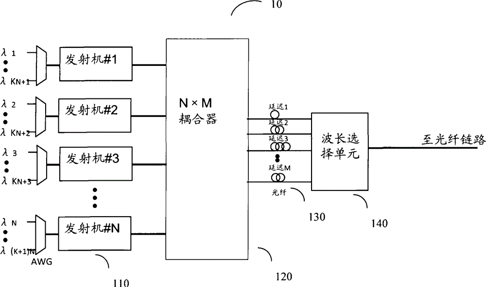
[0026] figure 1 A schematic structural diagram of a dense wavelength division multiplexing transmission experimental system 10 according to an embodiment of the present invention is shown. In this experimental system, it is necessary to distribute the wavelength channels of the transmitter to multiple delay lines to realize these wavelengths Channel decorrelation. The basic principle of the experimental system is that after the information sequences on different wavelength channels sent by the transmitter pass through different delay lines with sufficient length, these information sequences can be considered to be independent of each other.
[0027] as from figure 1 As can be seen in , the experimental system 10 includes N transmitters 110, N×M couplers 120 and M delay lines 130, where N and M are natural numbers. Each transmitter includes multiple wavelength channels. For example, the wavelengths of the wavelength channels included in transmitter #1 are λ 1 , lambda N+1 ...
no. 2 example
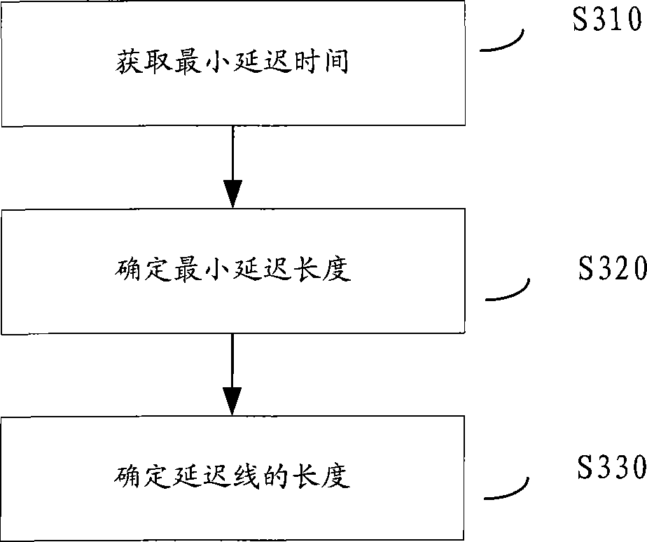
[0037] According to an embodiment of the present invention, a method for determining the delay line length in the DWDM transmission experimental system 10 is proposed. image 3 A flow chart of a method for determining the length of a delay line according to an embodiment of the present invention is shown.
[0038] as from image 3 As can be seen in the , the method includes:
[0039] Step S310: Obtain the minimum delay time τ min . The minimum delay time τ min It can be given in advance, or can be calculated according to the following formula:
[0040] τ min = i × 1 f 0 = i × 2 πDNΔλ α - - - ( 1 )
[0041] where D is the fiber dispersion coefficient, N is the number of...
no. 3 example
[0052] According to an embodiment of the present invention, a method for decorrelating channels in a dense wavelength division multiplexing transmission experimental system is proposed. Figure 4 A flowchart of a method for decorrelating channels according to an embodiment of the present invention is shown.
[0053] Such as Figure 4 As shown, the method includes the following steps:
[0054] S410: Provide dense wavelength division multiplexing transmission experimental system. as in the previous combination figure 1 As described, the experimental system 10 includes N transmitters 110, N×M couplers 120 and M delay lines 130, where N and M are natural numbers. Each transmitter includes multiple wavelength channels. For example, the wavelengths of the wavelength channels included in transmitter #1 are λ 1 , lambda N+1 ,...,λ kN+1 , the wavelengths of the wavelength channels included in transmitter #2 are λ 2 , lambda N+2 ,...,λ kN+2 etc., where the wavelength differenc...
PUM
 Abstract
Description
Claims
Application Information
 - Generate Ideas
- Intellectual Property
- Life Sciences
- Materials
- Tech Scout
- Unparalleled Data Quality
- Higher Quality Content
- 60% Fewer Hallucinations
Browse by: Latest US Patents, China's latest patents, Technical Efficacy Thesaurus, Application Domain, Technology Topic, Popular Technical Reports.
© 2025 PatSnap. All rights reserved.Legal|Privacy policy|Modern Slavery Act Transparency Statement|Sitemap|About US| Contact US: help@patsnap.com