Method for making optical fibre with low E-waveband and L-waveband loss wave peak

A wave band, optical fiber technology, applied in the field of optical fiber

Inactive Publication Date: 2008-10-29
OFS FITEL LLC
View PDF9 Cites 0 Cited by
  • Summary
  • Abstract
  • Description
  • Claims
  • Application Information

AI Technical Summary

Problems solved by technology

Unfortunately, since the range of wavelengths used has been extended to the L-band, balanced low loss cannot be a fact

Method used


Image

  • Method for making optical fibre with low E-waveband and L-waveband loss wave peak
  • Method for making optical fibre with low E-waveband and L-waveband loss wave peak
  • Method for making optical fibre with low E-waveband and L-waveband loss wave peak

Examples


Embodiment Construction

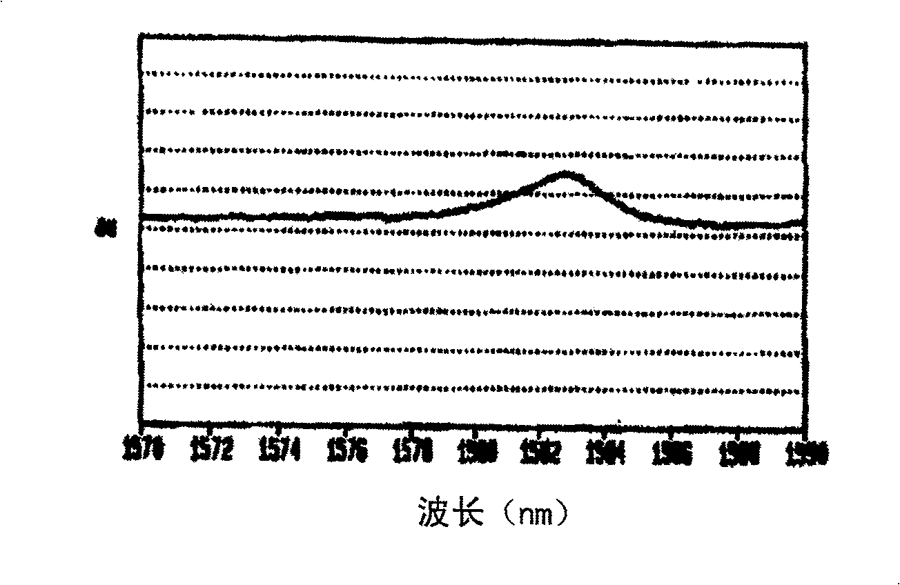
[0022] In the process of researching long-distance optical fiber transmission systems using light channels in the E-band (1360nm-1460nm) and L-band (1565nm-1625nm), the applicant found that there are previously unknown wavelengths at 1440nm, 1583nm and 1614nm. Known narrow and relatively small loss peak. figure 1 A typical loss peak at a wavelength of 1583nm is illustrated. The loss peaks at 1440nm and 1614nm are very similar in width and magnitude. Since these peaks are very narrow in width, they are difficult to be removed by gain equalizers in long-distance transmission systems. And while being relatively small, the loss is sufficient to cause signal dropouts in transmission channels of E-band and L-band long-distance DWDM optical fiber transmission systems. Applicants have further determined that these loss peaks are due to carbon contamination of the fiber.

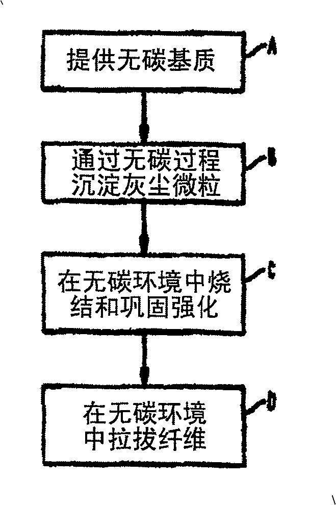
[0023] According to the present invention, optical fibers are manufactured by a process that strictly avoids ca...


PUM

PropertyMeasurementUnit
sizeaaaaaaaaaa

Abstract

This invention relates to optical fibers, and more particularly to methods of making optical fibers having low E-band and L-band loss peaks, and fibers made by such methods. Applicants have discovered the presence of loss peaks in optical fiber transmission systems using E-band and L-band wavelengths. In particular, they have found the existence of narrow loss peaks at 1440nm, 1583nm, and 1614nm. Since the peaks are relatively narrow, they are difficult to remove by ordinary gain equalizers in long-distance transmission systems, and even though the peaks are relatively small, they can cause signal drops in the transmission channel in amplified DWDM transmission systems. Applicants have further discovered that these loss peaks are all due to carbon contamination of the transmission fibers. Therefore, the manufacture of optical fibers should fundamentally prevent carbon contamination. This means eliminating carbonaceous reagents during the manufacture of prototype rods and tubes.

Description

technical field [0001] This invention relates to optical fibers, and more particularly to methods of making optical fibers having low E-band and L-band loss peaks, and fibers made by such methods. The method and fiber are especially useful for broadband transmission. Background technique [0002] In the field of modern telecommunication systems, optical fiber is a key component. Basically, an optical fiber is a thin glass filament capable of transmitting light signals carrying large amounts of information over long distances with little signal loss. Even better, the fiber can transmit all the same wavelengths (wavelengths of interest) with the same small loss. [0003] In its simplest form, a bundle of optical fibers is a bundle of small-diameter waveguides with a core of a first refractive index surrounded by a metal coating of a second (lower) refractive index (cladding) package. More typically, optical fibers are composed of high-purity silica with low dopant concentr...

Claims


Application Information

Patent Timeline
Patent Type & Authority Patents(China)
IPC IPC(8): G02B6/02H04B10/12C03B37/014C03C13/04
CPCC03B2201/07G02B6/02C03C13/045C03B2201/03C03B37/014
Inventor 罗伯特M·阿特肯丝阿里丝W·刘保罗克里斯滕森莫滕O·皮德森斯蒂戈N·那森简L·尼尔森加科布让梅志凯H·张
Owner OFS FITEL LLC
Why Eureka
Try Eureka