
Three-axis-system composite spinning device and spinning method for tow-apt-to-fall staple

A composite spinning and staple fiber technology, which is applied in the direction of continuous winding spinning machines, spinning machines, textiles and papermaking, etc., can solve the problems that do not involve kapok fiber triaxial composite spinning devices and methods, and achieve Excellent quality, strong controllability, convenient and innovative effects

Inactive Publication Date: 2012-01-11
DONGHUA UNIV
View PDF19 Cites 34 Cited by
  • Summary
  • Abstract
  • Description
  • Claims
  • Application Information

AI Technical Summary

Problems solved by technology

The prior art does not involve the three-axis composite spinning device and method of kapok fiber

Method used


Image

  • Three-axis-system composite spinning device and spinning method for tow-apt-to-fall staple
  • Three-axis-system composite spinning device and spinning method for tow-apt-to-fall staple
  • Three-axis-system composite spinning device and spinning method for tow-apt-to-fall staple

Examples


Embodiment 1

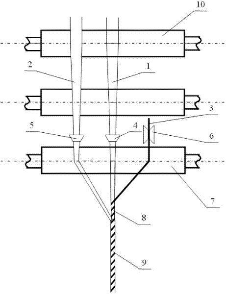
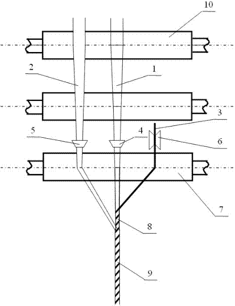
[0021] like figure 1 As shown, it is a structural schematic diagram of the first three-axis composite spinning device for easy-to-dump short fibers. The three-axis composite spinning device includes a ring spinning frame with a front roller 7, and the front roller Near the feeding jaw of 7, be provided with easily shedding short fiber sliver locator 4, cotton sliver locator 5 and long tow adjustable tension wheel 6. The relative positions between the easy-to-dandruff short fiber sliver positioner 4, the cotton sliver sliver positioner 5, and the adjustable tension wheel 6 for filament bundles can be adjusted. It is located between the sliver sliver positioner 5 and the adjustable tension wheel 6 of the filament bundle.

Embodiment 2

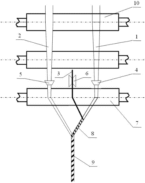
[0023] like figure 2 As shown, it is a schematic structural diagram of the second three-axis composite spinning device for easy-to-dump short fibers. The three-axis composite spinning device includes a ring spinning frame with a front roller 7, and the front roller Near the feeding jaw of 7, be provided with easily shedding short fiber sliver locator 4, cotton sliver locator 5 and long tow adjustable tension wheel 6. The relative positions between the easy-to-shred short fiber sliver locator 4, the cotton sliver locator 5 and the adjustable tension wheel 6 of the filament bundle can be adjusted, and the adjustable tension wheel 6 of the filament bundle is located at the easy Between the crumb short fiber sliver locator 4 and the cotton sliver sliver locator 5.

Embodiment 3

[0025] Using the three-axis composite spinning device of the easy-to-break short fiber described in Example 1, the kapok roving sliver and the cotton roving sliver are fed into the rear roller 10 of the ring spinning frame at a certain distance, and formed after drafting Straighten the parallel easy-to-shred short fiber strands (i.e. kapok strands) 1 and cotton strands 2; use the easy-to-shred short-fiber strands 1 and cotton strands 2 respectively with the easy-to-shred short-fiber locator 4 After being positioned with the sliver sliver positioner 5, it is fed into the jaws of the front roller 7, and the filament bundle (polyester textured yarn) 3 is directly fed into the jaws of the front roller 7 through the filament bundle adjustable tension wheel 6 to form a three-axis system Feeding: After the short fiber strands 1, cotton strands 2 and filament bundles 3 are output from the front roller 7 nip, the position of the staple strands 1 and the tension of the filament strands 3...


PUM


Abstract

The invention provides a three-axis-system composite spinning device and a spinning method for tow-apt-to-fall staple. The three-axis-system composite spinning method is characterized in that the method comprises the steps of: feeding roving silvers containing the tow-apt-to-fall staple and cotton roving silvers into the back roller of a ring spinning machine, and conducting drafting to form a tow-apt-to-fall staple strand and a cotton strand which stretch straight in parallel; after the tow-apt-to-fall staple strand and the cotton strand are respectively positioned by using a tow-apt-to-fall staple strand positioner and a cotton strand positioner, feeding the tow-apt-to-fall staple strand and the cotton strand into the jaw of a front roller and directly feeding filament adjustable tension pulley into the jaw of the front roller; and after the tow-apt-to-fall staple strand, the cotton strand and the filament are output from the jaw of the front roller, twisting the tow-apt-to-fall staple strand and the filament at a first converging point outside the jaw of the front roller to form a structural section, and twisting the structural section and the cotton strand at a second converging point to form a three-axis-system composite yarn. The device and the method provided by the invention has the advantages that not only can the content of the tow-apt-to-fall staples in the spun composite yarn be improved, but also the situations of fiber damage and tow falling can be effectively avoided.

Description

technical field [0001] The invention relates to a three-axis composite spinning device and spinning method for short fibers that are easy to fall off, and are suitable for short fibers that are easy to fall off, such as kapok fiber, kapok fiber, cotton linters, industrial noil, cotton noil, and industrial noil. Or reuse cotton fiber and the like. Background technique [0002] Because kapok fiber has a fiber hollowness of more than 80%, thin cell wall, short length, strong rigidity, and high appearance volume ratio, kapok fiber spinning has low strength, is easy to bend and break, and is difficult to form into yarn. The fiber wall is fragile, the fiber itself is short and light in weight, and there is a lot of dust, white flowers, and falling flowers during the yarn spinning process, and even after yarn and textiles are formed, there are still obvious debris phenomena. This is an important technical difficulty for spinning processing equipment, and it is also a major defect ...

Claims


Application Information

Patent Timeline
Patent Type & Authority Applications(China)
IPC IPC(8): D01H13/04D01H13/10D01H1/02
Inventor 于伟东杜赵群邓成亮付江于昊慧
Owner DONGHUA UNIV
Learn More