Catalyst injection method and catalyst injection device

A technology for injection devices and catalysts, applied in chemical instruments and methods, catalytic cracking, cracking, etc., can solve problems such as easy wear, unfavorable mixing, and inability to run for a long period of time, and achieve the goals of reducing wear, increasing reaction temperature, and reducing olefin content Effect

Active Publication Date: 2014-03-26
CHINA PETROLEUM & CHEM CORP +1
View PDF6 Cites 2 Cited by
  • Summary
  • Abstract
  • Description
  • Claims
  • Application Information

AI Technical Summary

Problems solved by technology

It can be seen that it is not suitable for the injection of FCC solid catalyst particles, and when it is injected downstream of the cracking reaction tube, it is not conducive to the mixing of the injected catalyst and the reaction mixture in the cracking tube, especially for the high-speed flow of gas-solid fluid in the FCC riser reactor ( Gas velocity 8-20 m / s), the injection pipe stretches into the cracking tube reactor, which is easy to wear and cannot run for a long period of time

Method used


Image

  • Catalyst injection method and catalyst injection device
  • Catalyst injection method and catalyst injection device
  • Catalyst injection method and catalyst injection device

Examples


Embodiment Construction

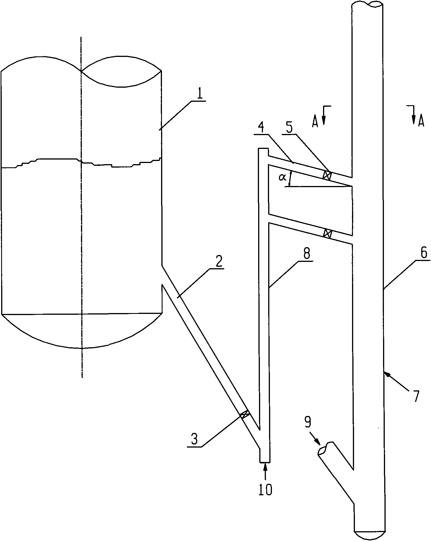
[0026] Such as figure 1 , a catalyst injection method, the catalytic cracking catalyst is injected into the container 1, through the inclined pipe 2 to the bottom of the standpipe 8, and then under the action of the lift gas 10, the catalyst is sent from the standpipe 8 to the injection pipe 4, under control It enters the FCC riser reactor 6 under the control of valve 5.

[0027] Such as figure 1 , a catalyst injection device, the bottom of the container 1 is connected to the inlet of the inclined catalyst tube 2, the outlet of the inclined catalyst tube 2 is connected to the inlet of the standpipe 8, the outlet of the standpipe 8 is connected to the inlet of the injection pipe 4, and the angle between the injection pipe 4 and the horizontal direction is For 30 °, there are 2 injection pipes 4.

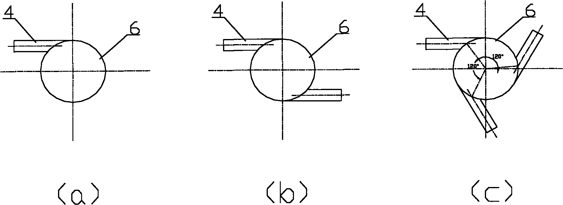
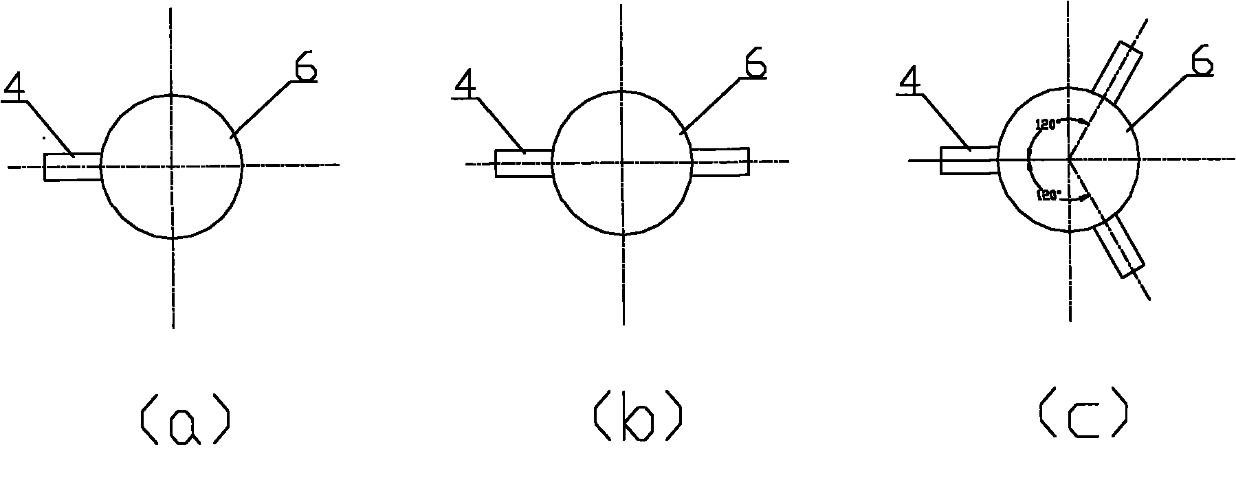
[0028] figure 2 , image 3 for figure 1 In the cross-sectional view of A-A, two-way or three-way methods are generally used to ensure that the catalysts at each injection port a...


PUM


Abstract

The invention discloses a catalyst injection method and a catalyst injection device. A catalyst to be injected is placed in a container; the catalyst is injected into a riser reactor from an injection pipe which forms an angle of 0 to 70 DEG C with a horizontal direction by using rising gas; and the catalyst is injected into the riser reactor from a radical or tangent line direction. The reaction temperature, activity of the catalyst and the flexibility of regulation of an agent to oil ratio are increased and the yield of a target product is increased.

Description

technical field [0001] The invention relates to catalytic cracking of hydrocarbon oil in the absence of hydrogen, in particular to a cracking catalyst injection method and device. Background technique [0002] Fluid catalytic cracking (FCC) is an important secondary processing method in the oil refining industry. In a conventional FCC riser reactor, the catalytic cracking reaction is carried out after the feedstock oil contacts with the high-temperature regenerated catalyst at 680-690°C in the lower part of the riser reactor. In order to adjust the reaction temperature of the riser reactor, the average activity of the catalyst in the reactor and the ratio of catalyst to oil, it is necessary to add a part of regenerated catalyst, spent catalyst or fresh catalyst to the riser reactor to adjust the reaction temperature and the ratio of catalyst to oil. [0003] CN101161618A discloses a cracking catalyst injecting method and device for the field of producing ketene and its deri...

Claims


Application Information

Patent Timeline
Patent Type & Authority Patents(China)
IPC IPC(8): C10G11/18B01J8/18
Inventor 张振千王龙延李国智闫鸿飞夏金法田耕
Owner CHINA PETROLEUM & CHEM CORP
Why Eureka
Try Eureka