Regeneratively cooled porous media jacket
A porous medium, cooling technology, applied in the direction of machine/engine, engine function, rocket engine device, etc., can solve the problem of not being able to provide proper cooling
- Summary
- Abstract
- Description
- Claims
- Application Information
AI Technical Summary
Problems solved by technology
Method used
Image
Examples
example 1
[0042] Example 1 - Lithographic method
[0043] exist Figure 5 The photolithographic fabrication method is outlined in . In the stacked and bonded lithographic fabrication method, a limited number of layers are fabricated which when stacked and bonded (along the axis of the engine) make up the combustion chamber, porous media passages, and pressure shell ) (in order from the inside of the engine to the outside of the engine). Along the thrust axis of the propeller, the chamber profile varies to impede flow through the throat region and to expand flow through the expansion nozzle to generate thrust.
[0044] The internal dimensions of the porous media vary to conform to the combustion chamber profile and the outer diameter of the porous media will vary to control the jacket gap and microfluidic geometry to minimize pressure drop across the jacket Control cooling. A three-dimensional porous media sheath is built in stacked layers and is typically fusion bonded (with appli...
example 2
[0058] Example 2 - Processing metal foam
[0059] refer to Figure 6 An alternative method of fabricating a regeneratively cooled porous media jacket, including machining and assembly, is described. This manufacturing method relies on more traditional mechanical design and manufacturing methods. Initially, the unassembled jacket is in the form of separate parts: inner wall 600 (which defines the combustion chamber), two halves of porous media 602 and 604 , and two halves of outer walls 606 and 608 . Candidate materials for inner wall 600 include, but are not limited to, copper, aluminum, nickel, nickel alloys, stainless steel, niobium, rhenium, tantalum, molybdenum, carbon, carbon-carbon composites, or alloys / combinations thereof. Materials with higher thermal conductivity are advantageous for certain applications; however, the chamber material is selected for the desired combustion process. Not all materials can be manufactured with conventional machining, so use appropr...
example 3
[0070] Example 3 - Model for the design of a regeneratively cooled jacket
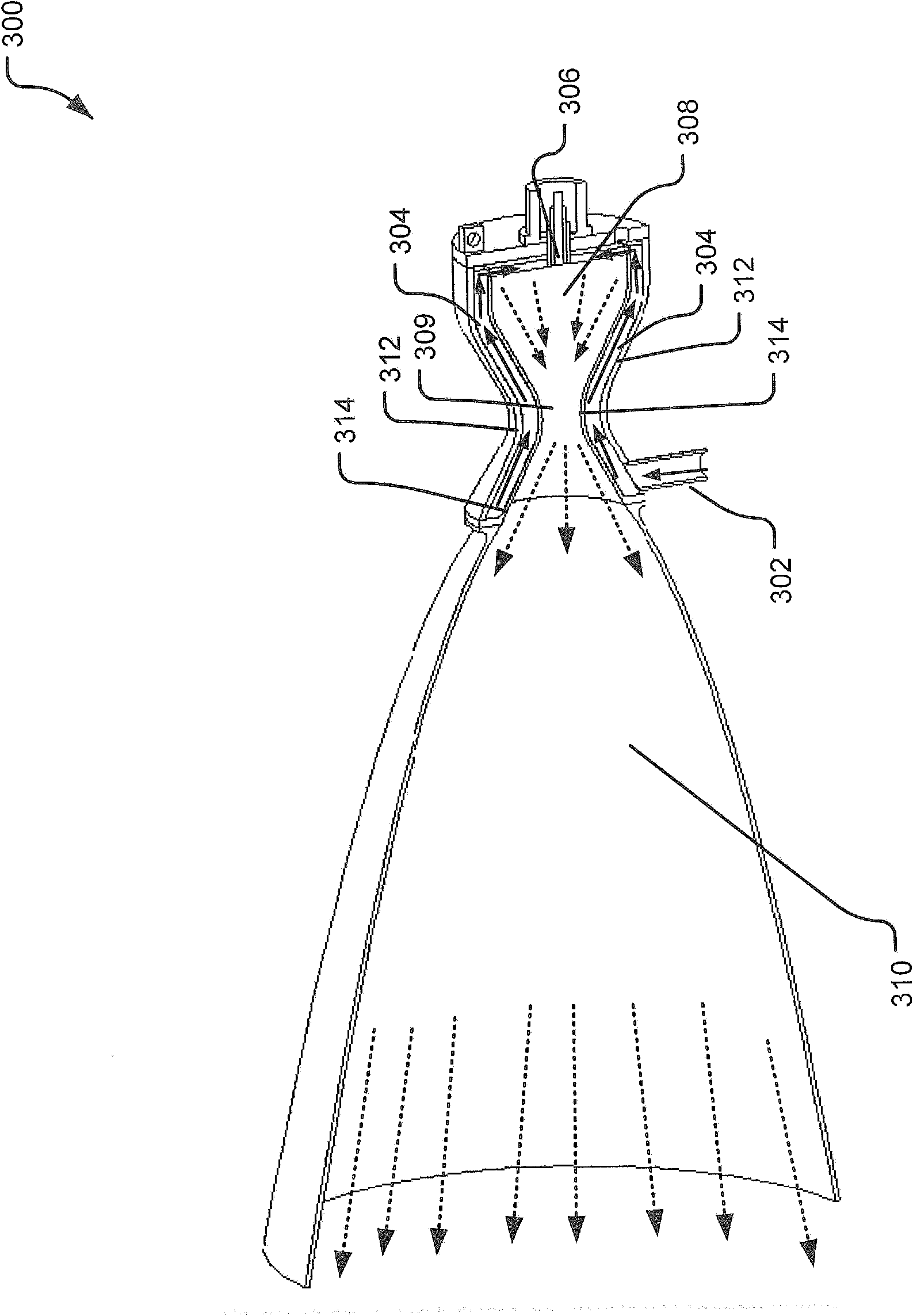
[0071] Disclosed herein is a system-level analytical fluid model for the inclusion of a porous media within a regeneratively cooled rocket combustion chamber jacket for the purpose of representing the porous media in this type of application to allow rocket thrusters to The ability of a gas phase propellant to function. In this example, the specific design problems of typically worst-case (in terms of cooling and jacket pressure drop capabilities) gas-phase NOFB unit propellant rocket motors are addressed, although it is also possible to address different types of motors on the basis of these teachings . Further details of NOFB unit propellants can be found in the already incorporated US Patent Application No. 12 / 268,266.
[0072] Typically, the thermal conductivity of the fluid limits the heat transfer into the regeneratively cooled combustion chamber. This then limits the cooling ability of the ...
PUM
| Property | Measurement | Unit |
|---|---|---|
| pore size | aaaaa | aaaaa |
| porosity | aaaaa | aaaaa |
| porosity | aaaaa | aaaaa |
Abstract
Description
Claims
Application Information
 - R&D
- Intellectual Property
- Life Sciences
- Materials
- Tech Scout
- Unparalleled Data Quality
- Higher Quality Content
- 60% Fewer Hallucinations
Browse by: Latest US Patents, China's latest patents, Technical Efficacy Thesaurus, Application Domain, Technology Topic, Popular Technical Reports.
© 2025 PatSnap. All rights reserved.Legal|Privacy policy|Modern Slavery Act Transparency Statement|Sitemap|About US| Contact US: help@patsnap.com


