
Cooling device

A technology of heat dissipation device and heating element, applied in cooling/ventilation/heating transformation, etc., can solve the problems of high cost, difficult maintenance, complex structure, etc., and achieve the effect of price concession, prevention of salt spray and sand dust, and price advantage

Active Publication Date: 2012-01-04
GUANGDONG MINGYANG WIND POWER IND GRP CO LTD
View PDF5 Cites 5 Cited by
  • Summary
  • Abstract
  • Description
  • Claims
  • Application Information

AI Technical Summary

Problems solved by technology

Complex structure, high cost and difficult maintenance

Method used


Image

  • Cooling device
  • Cooling device
  • Cooling device

Examples


Embodiment Construction

[0022] The present invention is described in detail below in conjunction with accompanying drawing:

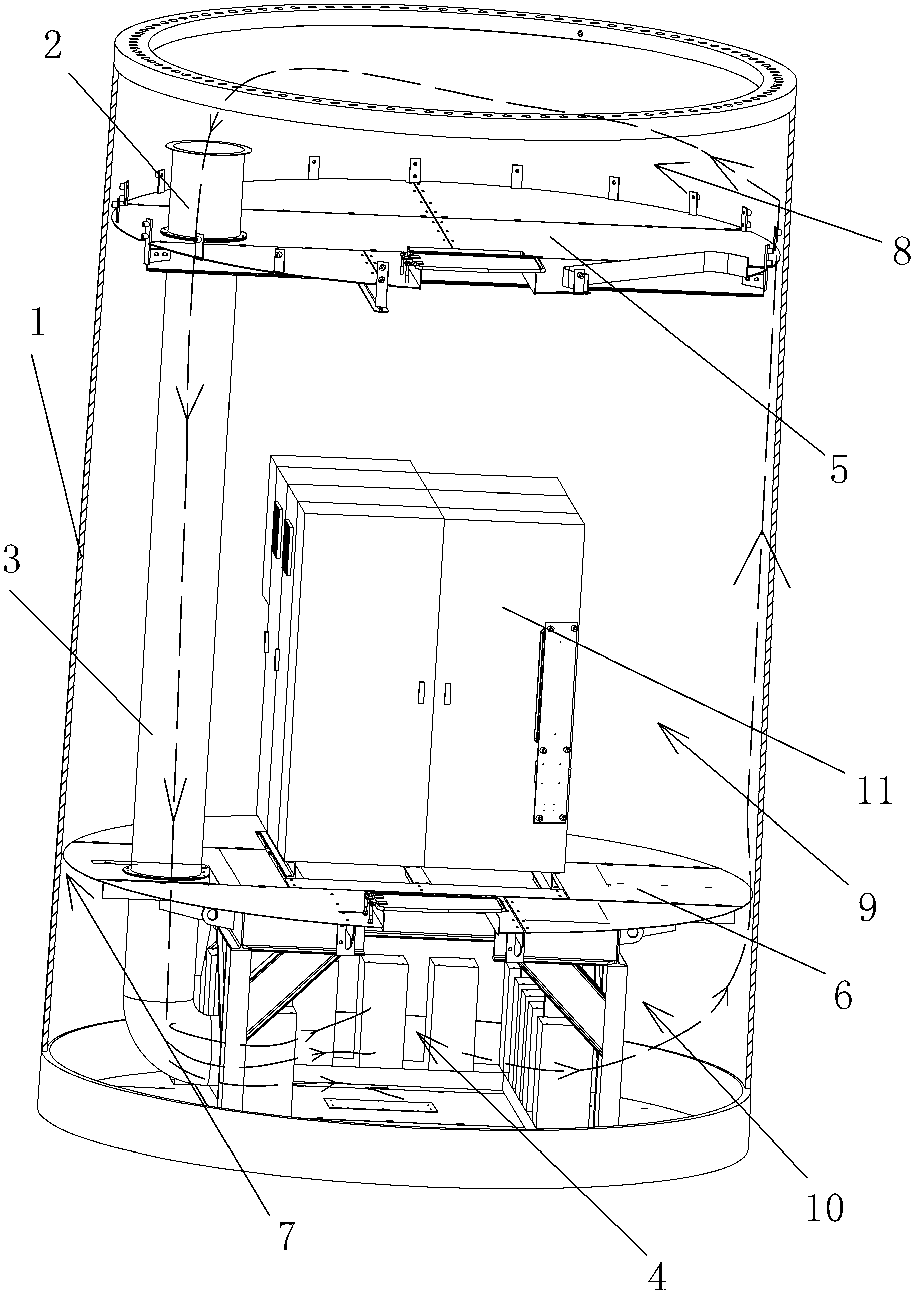
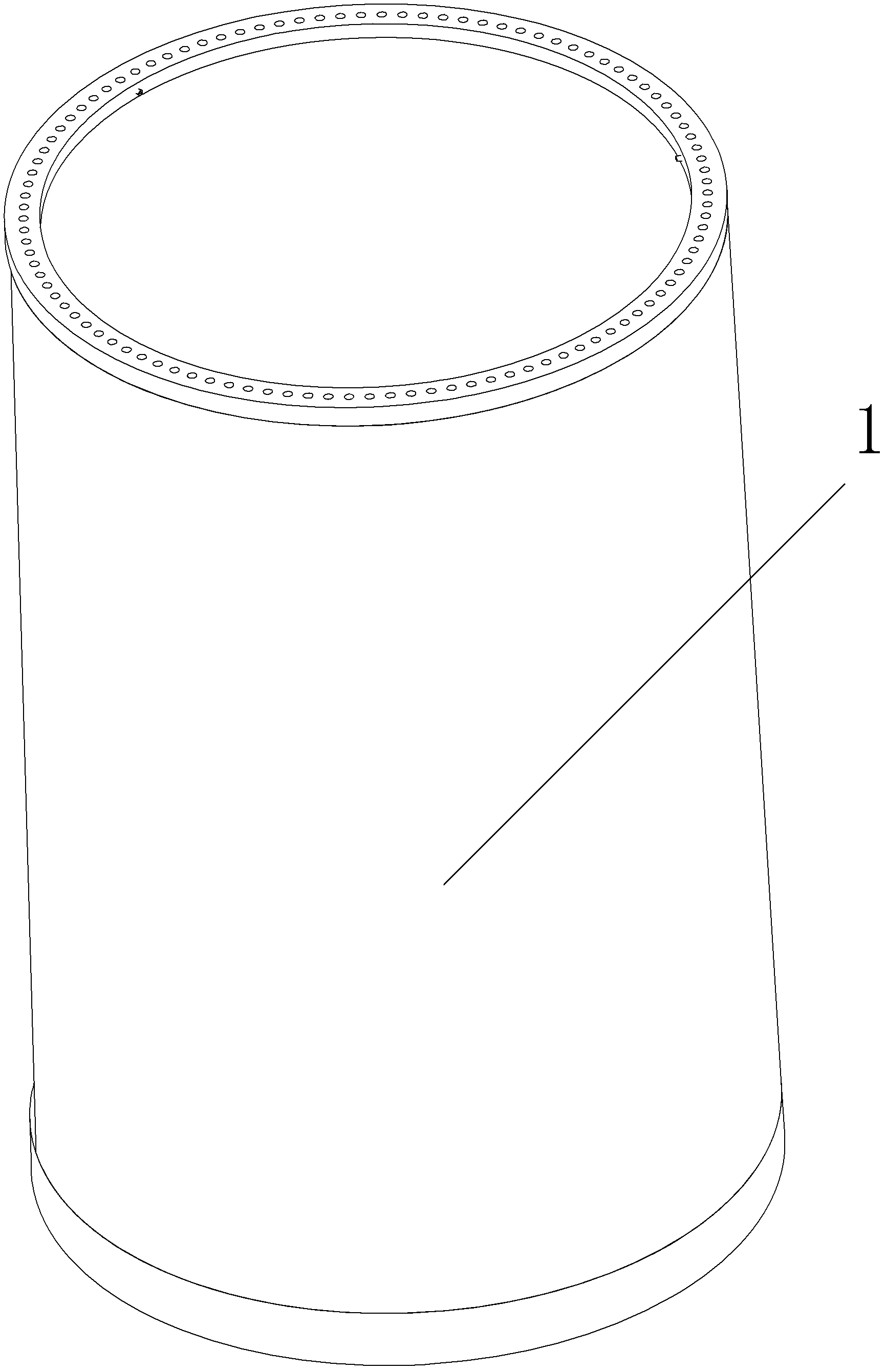
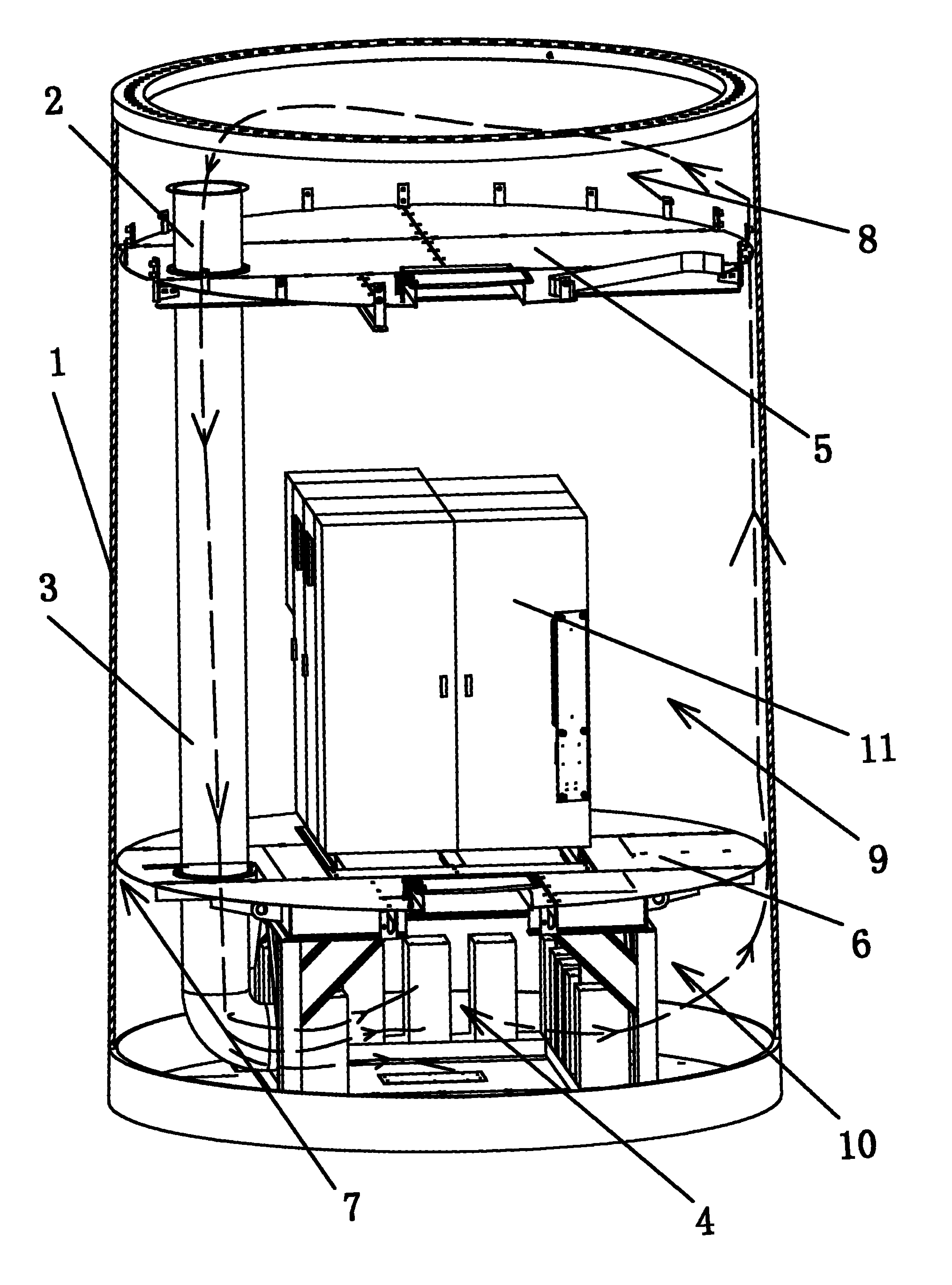
[0023] A heat dissipation device includes a closed tower tube 1 made of steel plate, the tower tube 1 is circular, the wall thickness of the tower tube 1 is 50-60 mm, and the height of the tower tube 1 is generally more than 30 meters. A fan 2 is arranged on the top of the tower 1 , and an air supply pipe 3 for sending the wind blown by the fan 2 to the bottom of the tower 1 is arranged on the side of the tower 1 . The upper opening of the air supply pipe 3 is connected to the outlet of the blower fan 2, and the lower end opening of the air supply pipe 3 faces the heating element 4 that needs heat dissipation. Then the fan 2 blows the cold air at the upper part of the tower 1 to the heating element 4 at the lower part of the tower 1 , thereby cooling the heating element 4 .

[0024] Since the tower 1 is a good conductor of heat transfer, the fan 2 is used to blow air on the u...


PUM


Abstract

The invention relates to a cooling device which comprises a closed tower barrel which is made of a steel plate, wherein the top of the tower barrel is provided with a fan, the side of the tower barrel is provided with a blast tube which is used for blowing air from the fan to the bottom of the tower barrel, the upper opening of the blast tube is connected with the outlet of the fan, and the lower opening of the blast tube faces to a heating element requiring heat dissipation. The cooling device provided by the invention has the advantages that the defects in the prior art are overcome, the wind power tower barrel is utilized to carry out heat dissipation, the structure is simple, the cost is low, and the maintenance is convenient.

Description

【Technical field】 [0001] The invention relates to a heat dissipation device. 【Background technique】 [0002] Since the heat generated on the surface of electrical components such as inverters and reactors inside the tower is 15kW, that is, the heat to be dissipated by the tower is 15kW. Because the tower tube is set up by the sea, the interior of the tower tube must be closed to prevent the erosion of salt spray in the seaside air. [0003] Using traditional air-cooling systems or water-cooling systems to dissipate heat requires a lot of manpower and material costs as well as continuous power consumption. The existing heating elements used for cooling towers are generally imported from Germany, and it costs 200,000 yuan to buy one in China plus tariffs. The structure is complicated, the cost is high, and the maintenance is difficult. [0004] The present invention is made under such circumstances. 【Content of invention】 [0005] The object of the present invention is t...

Claims


Application Information

Patent Timeline
Patent Type & Authority Applications(China)
IPC IPC(8): H05K7/20
Inventor 李勇锋李健吴昊程斌
Owner GUANGDONG MINGYANG WIND POWER IND GRP CO LTD
Learn More