Motor-driven four-way reversing valve

A four-way reversing valve, motor-driven technology, applied in multi-way valves, valve details, valve devices, etc., can solve the problem of inability to reverse the rotor action timing, time and rotation angle control, four-way valve does not have cost advantages, Problems such as the structure of the four-way valve are not disclosed, so as to achieve the effect of easy product quality assurance, saving of motor cost and control circuit cost, and high operation reliability.

Inactive Publication Date: 2012-01-04
GUANGDONG HANGJI METAL PRODUCT INDUSTRIES CO LTD
View PDF9 Cites 5 Cited by
  • Summary
  • Abstract
  • Description
  • Claims
  • Application Information

AI Technical Summary

Problems solved by technology

[0005] 3) In addition to the electromagnetic coil, the number of other parts reaches more than 35, with many parts and complex structure;
[0006] 4) The assembly process is complicated, especially there are more than 16 welding parts, the requirements for welding equipment are high, and the quality is difficult to control;
[0007] 5) High material and processing costs
However, this patent document only discloses the structure of a four-way valve driven by a servo motor, but does not disclose the structure of a four-way valve driven by a motor with other characteristics
According to the structure of the four-way valve defined in the technical solution, those skilled in the art can also directly judge that the technical solution can only be driven by a servo motor. If a motor with other characteristics is used such as a synchronous motor to drive, There will be problems that the action timing, time and rotation angle of the reversing rotor cannot be controlled.
In addition, those skilled in the art also know that the driving and control of the servo motor requires a relatively complicated control circuit, which makes such a four-way valve not actually cost-effective

Method used


Image

  • Motor-driven four-way reversing valve
  • Motor-driven four-way reversing valve
  • Motor-driven four-way reversing valve

Examples


Embodiment 1

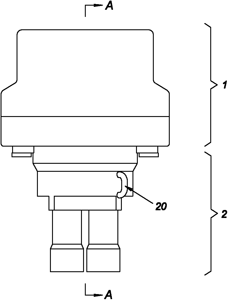
[0061] Such as image 3 , Figure 4 As shown, the motor-driven four-way reversing valve of this embodiment includes a driving device 1 and a four-way reversing valve body 2 connected together. in:

[0062] a) The driving device 1 includes: a box cover 3, a box seat 4, a synchronous motor 5, a cam member 6, a first microswitch 7 as the first in-position switch, a second microswitch 8 as the second in-position switch, and a circuit board 9 , heating power supply line 10 , cooling power supply line 11 and common line 12 .

[0063] The box cover 3 and the box seat 4 are connected together by screws to form a box body; the synchronous motor 5, the cam member 6, the first microswitch 7, the second microswitch 8, and the circuit board 9 are all in the box body; the cam member 6 is coaxially installed on the output shaft 13 of the synchronous motor 5, and serves as a coupling between the output shaft 13 and the following input shaft 18; the first microswitch 7 and the second micros...

Embodiment 2

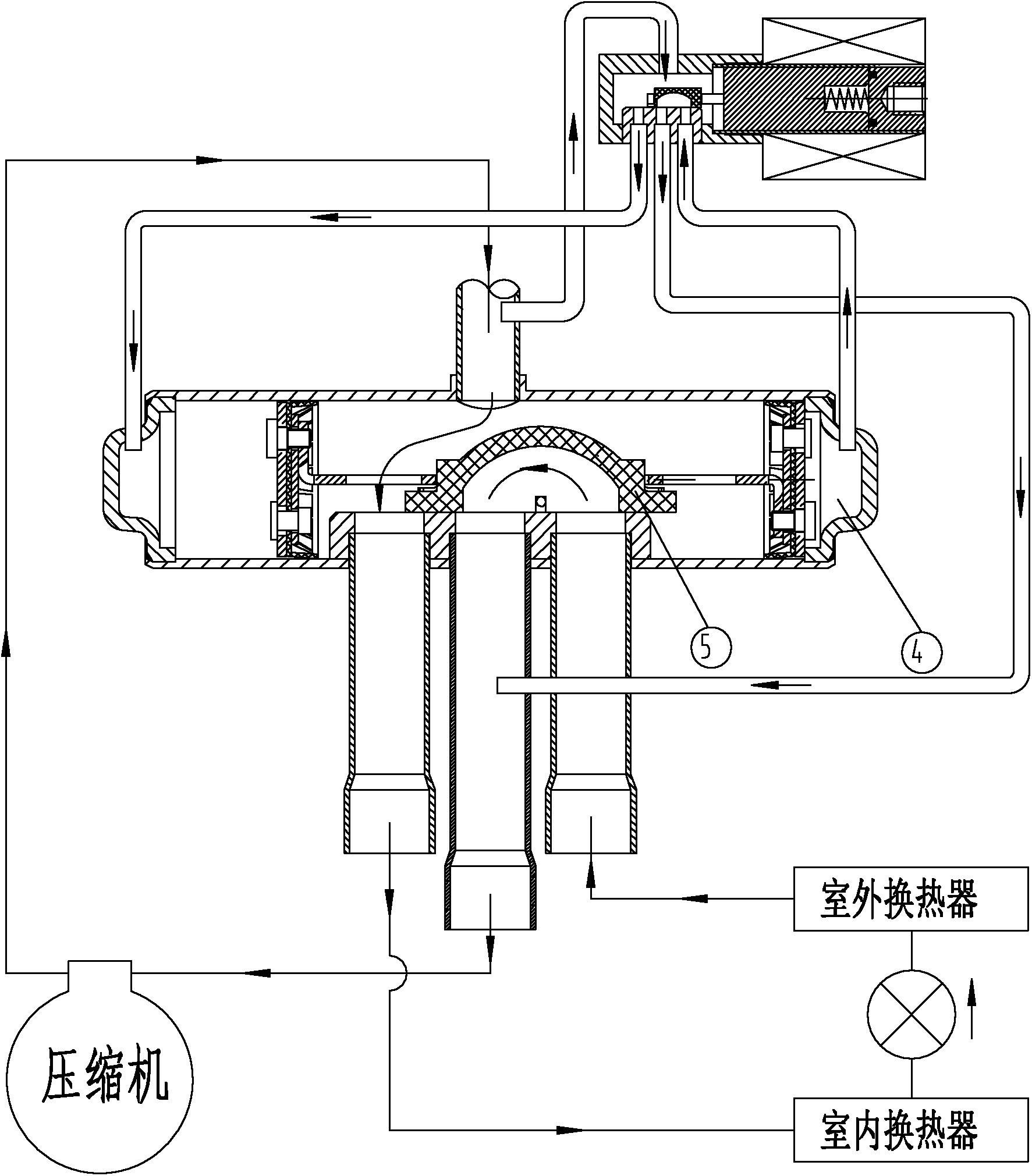
[0071] Such as Figure 17 , Figure 18 As shown, the difference between this embodiment and Embodiment 1 is that the other end of the input shaft 18' is directly inserted into the slot on the reversing rotor 16', and the two do not transmit through metal sheets. In addition, a sealing ring 19' is provided between the valve body gland 15' and the valve body casing 14'.

Embodiment 3

[0073] Such as Figure 19 , Figure 20 As shown, the difference between this embodiment and Embodiment 1 lies in: the shape of the reversing rotor 16 ″ and the first nozzle 21 ″, the second nozzle 22 ″, and the third nozzle 23 ″ on the valve housing 14 ″ It is different from the drawing direction of the fourth nozzle 24 ". Specifically, the reversing rotor 16 "is integrated with the input shaft 18", and a partition 26 "is formed on the reversing rotor 16 ", and the partition 26 "is arranged along the diameter direction of the reversing rotor 16 ", and is perpendicular to The end face of the reversing rotor 16", the two sides of the partition plate 26" correspond to the two refrigerant passages of the reversing rotor 16"; the first nozzle 21", the second nozzle 22", the third nozzle 23" and the second nozzle Four nozzles 24 " are drawn from the direction perpendicular to the input shaft 18 " of the reversing rotor 16 " on the valve housing 14 ". Such as Figure 20 As shown,...


PUM


Abstract

The invention provides a motor-driven energy-saving four-way reversing valve with a compact structure and lower production cost. The motor-driven energy-saving four-way reversing valve comprises a synchronous motor and a cam piece driven by the synchronous motor; a first location switch and a second location switch are arranged close to the cam piece; the cam piece is provided with a cam which makes the on-off state of the first location switch always opposite to that of the second location switch and making the on-off states of the first location switch and the second location switch simultaneously changed once when the cam piece rotates 1 / 4 cycle; a contact at one end of the first location switch is electrically connected with a heating supply line; a contact at one end of the second location switch is electrically connected with a refrigerating supply line; a contact at the other end of the first location switch and a contact at the other end of the second location switch are electrically connected with one electrode of the synchronous motor; and the other electrode of the synchronous motor is electrically connected with a common line. The motor-driven energy-saving four-way reversing valve has the advantages of short power-on time, high action reliability, simple structure, simplified assembling process, low cost and the like.

Description

technical field [0001] The invention relates to a four-way reversing valve for heating and cooling air conditioners. Background technique [0002] Such as figure 1 , figure 2 As shown, the heating and cooling air conditioner uses a traditional electromagnetic four-way reversing valve to change the flow direction of the refrigerant during the mutual conversion of cooling and heating. The shortcomings of the traditional electromagnetic four-way reversing valve are: [0003] 1) After the conversion from cooling to heating is completed, the electromagnetic coil is still energized, which does not save energy, and at the same time, it is easy to burn out due to the long power-on time; [0004] 2) The electromagnetic pilot valve is used to control the pressure difference on both sides of the spool valve to achieve reversing. There are many intermediate links, and the spool valve is easy to get stuck without reversing; [0005] 3) In addition to the electromagnetic coil, the nu...

Claims


Application Information

Patent Timeline
IPC IPC(8): F16K31/04F16K31/524F16K11/08
Inventor 胡明军王浩生罗建英
Owner GUANGDONG HANGJI METAL PRODUCT INDUSTRIES CO LTD
Why Eureka
Try Eureka