Wire rod, steel wire and their manufacturing method
A manufacturing method and wire rod technology, applied in the field of steel wire, can solve the problems of increased production cost and huge investment in equipment, etc.
- Summary
- Abstract
- Description
- Claims
- Application Information
AI Technical Summary
Problems solved by technology
Method used
Image
Examples
no. 1 Embodiment approach
[0065] (Composition of the wire)
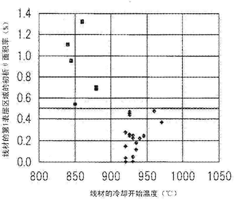
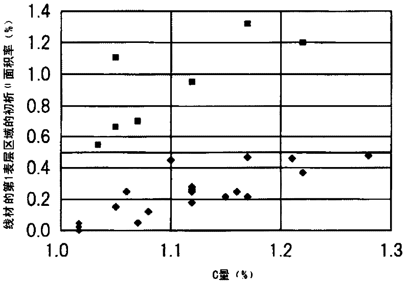
[0066] The first embodiment of the present invention relates to a wire rod in which an area of 0.5% or less of the center region of a cross section perpendicular to the longitudinal direction of the wire rod and an area of 0.5% or less of the surface region (first surface layer region) of the cross section are initially divided. Occupied by analysis of cementite structure.
[0067] According to the research of the present inventors, the ratio of proeutectoid cementite in the surface region of the wire rod and the central region of the wire rod before wire drawing is related to the ductility of the steel wire after wire drawing. If the area ratio of cementite in the surface layer region of the wire rod can be suppressed to 0.5 % or less, the ductility of the steel wire obtained by wire drawing is improved, and by suppressing the area ratio of cementite in the central region of the wire rod to 0.5% or less, wire breakage during drawing can ...
no. 2 Embodiment approach
[0126] (composition of steel wire)
[0127] A second embodiment of the present invention is a steel wire obtained by drawing the wire rod described in the first embodiment, having a diameter of 0.1 to 0.4 mm and a tensile strength of 4200 MPa or more. Proeutectoid cementite occupies 0.5% or less of the surface region (second surface region) of the cross section of the steel wire perpendicular to the longitudinal direction of the steel wire.
[0128] Here, the second surface layer region refers to the region from the surface layer of the steel wire to 10 μm.
[0129] (Manufacturing conditions of steel wire)
[0130] Such a steel wire can be obtained by drawing the wire rod described in the first embodiment, heating it to 900°C or higher, and introducing the heated wire rod into a lead bath or a fluidized bed at 500-600°C at least once. The steel wire that starts to cool in the middle is toughened, and then cold drawn.
no. 3 Embodiment approach
[0132] (composition of steel wire)
[0133] A third embodiment of the present invention is a steel wire having a diameter of 0.8 to 8 mm and a tensile strength of 1800 MPa or higher obtained by drawing the wire rod described in the first embodiment having a diameter of 5 to 16 mm. The area of 0.5% or less of the surface region (third surface region) of the cross section of the steel wire perpendicular to the longitudinal direction of the steel wire is occupied by proeutectoid cementite.
[0134] Here, the third surface layer region refers to the region from the surface layer of the steel wire to 20 μm.
[0135] (Manufacturing conditions of steel wire)
[0136] Such a steel wire can be obtained by cold drawing the wire rod described in the first embodiment.
[0137] The steel wire obtained in this way can be used directly after drawing, but it can also be processed as follows: (1) after drawing, implement bluing treatment, hot drawing, hot-dip galvanizing or hot-dip galvani...
PUM
| Property | Measurement | Unit |
|---|---|---|
| Thickness | aaaaa | aaaaa |
| Diameter | aaaaa | aaaaa |
| Tensile strength | aaaaa | aaaaa |
Abstract
Description
Claims
Application Information
 - R&D
- Intellectual Property
- Life Sciences
- Materials
- Tech Scout
- Unparalleled Data Quality
- Higher Quality Content
- 60% Fewer Hallucinations
Browse by: Latest US Patents, China's latest patents, Technical Efficacy Thesaurus, Application Domain, Technology Topic, Popular Technical Reports.
© 2025 PatSnap. All rights reserved.Legal|Privacy policy|Modern Slavery Act Transparency Statement|Sitemap|About US| Contact US: help@patsnap.com


