
Resource configuration method and device for backhaul link control channel information

A technology for controlling channel information and backhaul links, applied in transmission path sub-channel allocation, signaling allocation, pilot signal allocation, etc., can solve problems such as no clear control resource allocation scheme, and achieve flexible design and configuration, Taking into account the effect of standard design

Active Publication Date: 2011-12-28
DATANG MOBILE COMM EQUIP CO LTD
View PDF3 Cites 20 Cited by
  • Summary
  • Abstract
  • Description
  • Claims
  • Application Information

AI Technical Summary

Problems solved by technology

[0009] At present, in the LTE-A system, there is no specific control resource configuration scheme in the case where CSI-RS and DM-RS exist in the R-PDCCH

Method used


Image

  • Resource configuration method and device for backhaul link control channel information
  • Resource configuration method and device for backhaul link control channel information
  • Resource configuration method and device for backhaul link control channel information

Examples


Embodiment Construction

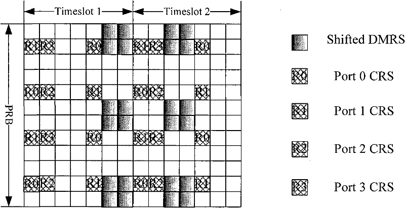
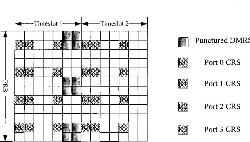
[0034] In the LTE-A system (also known as Release 10), a relay node (RN) is introduced in order to improve system throughput and increase network coverage. The link between the relay node and the eNB is called a backhaul link (backhaul link). On the backhaul link, the eNB uses a dedicated control channel R-PDCCH to transmit related control signaling to the relay. The DMRS pilot signal positions of more than 2 ports in the R-PDCCH area always exist, and there may also be CSI-RS,

[0035]In this case, according to the original version 8 mapping scheme, it is impossible to map all available areas of the R-PDCCH into REGs (Resource Element Groups, resource element groups). The technical solution of the embodiment of the present invention will provide a specific resource configuration solution of R-PDCCH in this case, so as to simplify the specification design, and can flexibly design and configure the relay link control channel according to the requirements of the actual system. ...


PUM


Abstract

The present invention discloses a method and device for resource allocation of backhaul link control channel information. Upon application of technical solution proposed by embodiment of this invention and based on the condition of introducing DMRS and CSI-RS, make remaining REs in OFDM symbol that contains REs for transmitting CSI-RS and / or DM-RS constitute REG to transmit backhaul link control channel information or abandon them, thus, on the basis of maximizing the reservation of existing LTE system specification, specifying resource allocation scheme of backhaul link control channel information in corresponding physical resource block, giving consideration to both simple specification design and full utilization of resources, and realizing flexible design and allocation in light of the demand of real system.

Description

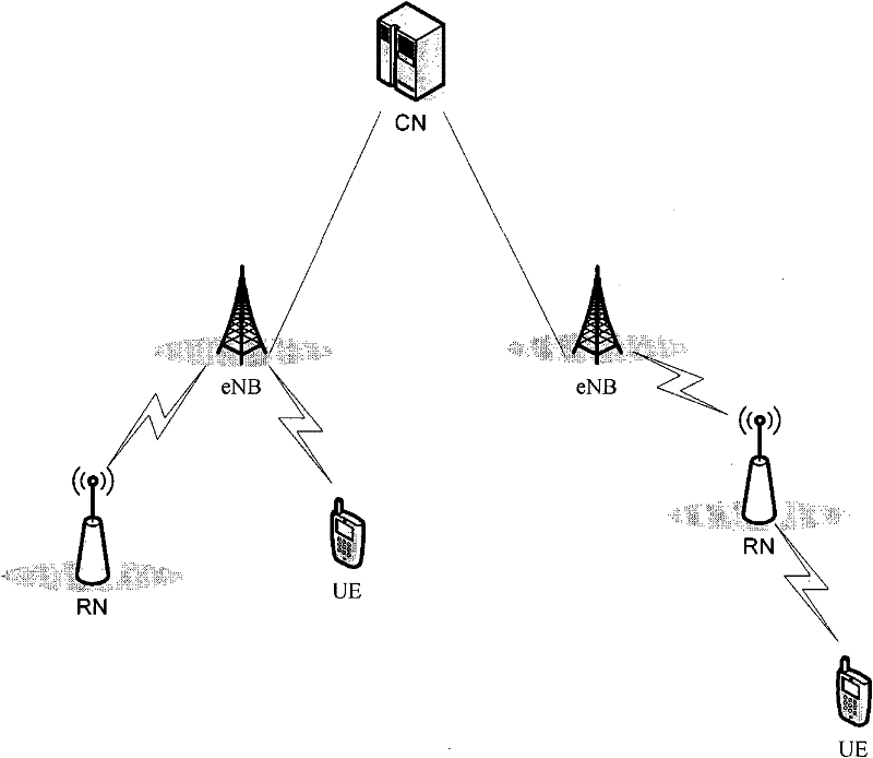
technical field [0001] The embodiments of the present invention relate to the field of communication technologies, and in particular, to a resource configuration method and device for backhaul link control channel information. Background technique [0002] The schematic diagram of the network structure of the LTE-A (Long Term Evolution Advanced) system is as follows figure 1 As shown, eNB (evolved Node B, evolved base station) is connected to the core network (Core Net, CN) through a wired interface, RN (Relay Node, relay node) is connected to the eNB through a wireless interface, UE (User Equipment, User equipment) is connected to RN or eNB through a wireless interface. [0003] Generally, there are two types of pilot signals in the LTE (Long Term Evolution, long-term evolution) system (that is, commonly referred to as version 8), that is, reference signals (Reference Signal, RS): common pilot signals (Common Reference Signal, CRS) And user-specific reference signal (Dedi...

Claims


Application Information

Patent Timeline
Patent Type & Authority Applications(China)
IPC IPC(8): H04W28/26H04W72/04
CPCH04W72/04H04L5/0048H04W84/047H04W72/044H04L5/0053H04L27/261H04L5/0007
Inventor 刘珂珂沈祖康潘学明王立波肖国军
Owner DATANG MOBILE COMM EQUIP CO LTD
Learn More