Optical module with strong light protection function

A protection function and optical module technology, applied in the field of optical communication, can solve the problems affecting the normal operation of passive optical network systems, economic losses of network managers and customers, breakdown and damage of optical receiving components, etc., to simplify maintenance work, reduce Maintenance cost, the effect of reducing the number of use

Active Publication Date: 2011-12-28
HISENSE BROADBAND MULTIMEDIA TECH
View PDF4 Cites 17 Cited by
  • Summary
  • Abstract
  • Description
  • Claims
  • Application Information

AI Technical Summary

Problems solved by technology

In the actual application process, when the receiving end of the optical module receives a strong optical signal, the optical receiving component is often damaged due to the lack of high-voltage protection measures in the receiving end circuit, resulting in the failure of the optical module. It affects the normal operation of the passive optical network system, and also brings large economic losses to network managers and customers

Method used


Image

  • Optical module with strong light protection function
  • Optical module with strong light protection function
  • Optical module with strong light protection function

Examples


Embodiment 1

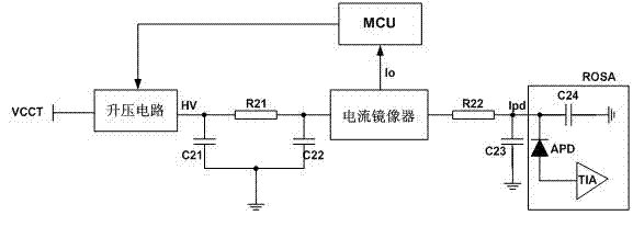
[0022] Embodiment 1. In this embodiment, in order to solve the problem that the receiving end of the optical module is easily broken down and damaged when the receiving end of the optical module is input by strong light, a high-voltage protection circuit is designed on the receiving end of the optical module. See figure 1 As shown, it is mainly composed of boost circuit, current mirror, current limiting resistor R22 and MCU. Among them, the input terminal of the boost circuit is connected to the DC power supply VCCT, and after the DC power supply VCCT is boosted and converted, the output high voltage HV is transmitted to the current mirror, and the high voltage output by the current mirror is transmitted to the optical receiver through the series current limiting resistor R22 Response current output of component ROSA. An avalanche photodiode APD and a transimpedance amplifier TIA are packaged in the light receiving component ROSA. The light receiving component ROSA receives th...


PUM


Abstract

The invention discloses an optical module with a blaze protection function. The optical module comprises a light reception assembly used for receiving a light signal, a boost circuit, a current mirror device and an MCU. The boost circuit sends high voltage generated by the boost circuit to a response current output terminal of the light reception assembly through the current mirror device and a current-limiting resistor. The current mirror device receives response current outputted by the light reception assembly, and sends the response current to the MCU after zoom processing. The MCU connects with boost voltage, and adjusts high voltage amplitude outputted by the boost circuit. According to the invention, a high voltage protection circuit is designed at a receiving end of the optical module, so that when a blaze reaches, the light reception assembly is prevented from breakdown and damage, and the optical module is effectively protected. At the same time, through employing a high integrated level transmit-receive one body chip to construct a module circuit, a circuit board dimension is reduced, a SFP interface packaging form is adapted, support of a digital diagnosis function is completed, and maintenance cost of a whole is reduced.

Description

technical field [0001] The invention belongs to the technical field of optical communication, and in particular relates to an optical module that realizes a high-voltage protection function for an optical receiving component when strong light is input at a receiving end. Background technique [0002] Passive optical network technology (PON) is a point-to-multipoint optical access technology. It is the best transmission medium to realize "triple play" and solve the "last mile" of the information highway. Video integrated service access function. The PON system consists of an OLT (Optical Line Termination) at the central office, an ONU / ONT (Optical Network Unit / Optical Network Termination, Optical Network Unit / Optical Network Termination) at the user side, and an ODN (Optical Network Terminal) connected between them. Distribution Network, optical distribution network). Among them, the Ethernet passive optical network EPON is a mature optical passive access network technology...

Claims


Application Information

Patent Timeline
Patent Type & Authority Applications(China)
IPC IPC(8): H04B10/148H04B10/158H02H3/20H04B10/69
Inventor 郑龙
Owner HISENSE BROADBAND MULTIMEDIA TECH
Why Eureka
Try Eureka