Pipeline a/d converter and its digital correction method with overflow flag

A pipeline and converter technology, applied in the direction of analog/digital conversion calibration/testing, etc., can solve the problem that A/D conversion samples cannot be digitally corrected, multi-time, etc., so as to reduce the correction time, reduce the number, and improve the correction accuracy.

Active Publication Date: 2011-12-28
ZHEJIANG UNIV
View PDF1 Cites 18 Cited by
  • Summary
  • Abstract
  • Description
  • Claims
  • Application Information

AI Technical Summary

Problems solved by technology

[0009] However, this pipeline A / D converter structure has the following problems: the digital output of the A / D converter does not have an overflow flag to indicate positive overflow or negative overflow respectively. When the input signal is greater than +V ref When the digital output is all 1, when the input signal is less than -V ref When the digital output is all 0
However, this digital background correction method has the following disadvantages: (1) There is a mismatch between two small capacitors split by a sampling capacitor due to process deviation, and the error caused by this mismatch exists as noise in the entire Nyquist frequency band ;(2) The correction level is only in the input signal range [-3 / 8V ref , +3 / 8V ref ], which means that most of the A / D conversion samples cannot be used for digital correction; (3) the correction level is corrected step by step, and the total correction time is equal to the correction required by each correction level The sum of the time, it takes more time to complete a digital background correction

Method used


Image

  • Pipeline a/d converter and its digital correction method with overflow flag
  • Pipeline a/d converter and its digital correction method with overflow flag
  • Pipeline a/d converter and its digital correction method with overflow flag

Examples


Embodiment Construction

[0049] In order to describe the present invention more specifically, the pipeline A / D converter and its digital correction method of the present invention will be described in detail below in conjunction with the accompanying drawings and specific embodiments.

[0050] Such as Figure 11 As shown, a 14-bit pipeline A / D converter includes 12 1.5-bit pipeline sub-levels and a 2.5-bit Flash A / D converter.

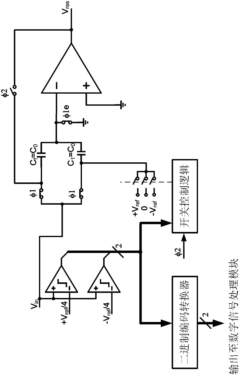
[0051] Such as Figure 4 As shown, the 1.5-bit pipeline sub-stage consists of an operational amplifier, a binary code converter, a switch control logic, a ground switch, a feedback switch, a feedback capacitor, an idle switch, an idle capacitor, a sampling capacitor, two Sampling switch, two three-selection switches and two comparators; among them, the non-inverting input terminal of the operational amplifier is grounded, the inverting input terminal of the operational amplifier is connected to one terminal of the grounding switch, and the feedback capacitor C f One end of t...


PUM


Abstract

The invention discloses a digital correcting method with an overflow marker position of a production line A / D (analog to digital) converter. The method comprises the following steps: (1) applying dither signals on each correction level in the production line A / D converter; (2) carrying out A / D conversion on each production line sub level, and generating and outputting signals and binary codes; (3) treating the output signals of each correction level to obtain correction parameters; and (4) carrying out coding rebuilding on the binary codes according to the correction parameters to obtain the A / D digital codes with two overflow marker positions. Simultaneously the invention also discloses the production line A / D converter for the method. The production line A / D converter comprises a plurality of overflow sub levels and a Flash A / D converter. According to the invention, through expanding the allowed input range of the production line sub levels and applying dither signals with a greatervalue of amplitude, errors caused by threshold voltage misalignment, capacitance mismatch and the operation of limited open-loop gains can be corrected, the correction time is short, the correction accuracy is high, and the positive overflow and negative overflow can be marked respectively.

Description

technical field [0001] The invention belongs to the technical field of analog-to-digital conversion, and in particular relates to a pipeline A / D converter and a digital correction method with an overflow flag. Background technique [0002] The A / D converter with pipeline structure is currently the most popular high-speed and high-resolution A / D converter structure, so high-speed and high-resolution pipeline A / D converter is widely used in key circuits such as wireless communication, image and voice signal processing. [0003] Stephen H. Lewis and Paul R. Gray proposed a pipelined A / D converter in a paper titled A Pipelined 5MHz 9b ADC (International Solid-State Circuits Conference, IEEE, 1987). The pipeline A / D converter amplifies the signal step by step through the cascaded pipeline sub-stages so that the pipeline comparators at all levels can compare. By combining the results of the pipeline A / D conversion at all levels, the digital value of the entire A / D converter system...

Claims


Application Information

Patent Timeline
IPC IPC(8): H03M1/10
Inventor 何乐年孙可旭
Owner ZHEJIANG UNIV
Why Eureka
Try Eureka