High-speed component distributing device

A technology of distributing devices and components, applied in sorting and other directions, can solve the problems of limited distributing speed, reduced reliability, and static electricity, and achieve the effect of reducing load inertia, reducing power requirements, and eliminating static electricity.

Active Publication Date: 2013-09-11
SHENZHEN HI TEST SEMICON EQUIP
View PDF6 Cites 0 Cited by
  • Summary
  • Abstract
  • Description
  • Claims
  • Application Information

AI Technical Summary

Problems solved by technology

But the disadvantages are: (1) The path length of the electronic components from the inlet of the test distributing pipe to the outlet of the distributing pipe is longer, resulting in a longer time for the electronic components to pass through this path at a certain speed, and the high speed is limited
(2) Due to the need to realize the mobile distribution of the two-dimensional coordinate distribution of the plane or spherical surface, two sets of distribution devices must be used. Although the purpose of optimizing the distribution time according to the frequency of occurrence is achieved, it takes up a lot of space and the actuators (such as servo motors, etc.) a total of 4 sets are required, and 4 sets of guide rails and corresponding mechanical parts are also required, and the total cost is relatively high
Its disadvantages are: (1) In order to achieve the purpose of spherical two-dimensional mobile positioning, two driving motors are required, and the second motor needs a load to drive the first motor to move, which results in a large inertia of the second motor load , it is difficult to realize the material distribution movement of high-speed start-stop positioning, so that the material distribution speed is limited
(2) Since the motor needs to move, its power supply cable and communication cable are prone to fatigue or wear due to high-speed movement, resulting in reduced reliability of motor control; and static electricity, which damages the electronic components that are distributed.

Method used


Image

  • High-speed component distributing device
  • High-speed component distributing device
  • High-speed component distributing device

Examples


Embodiment Construction

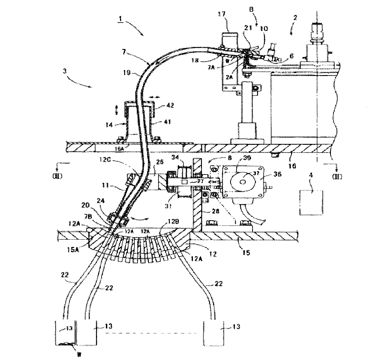
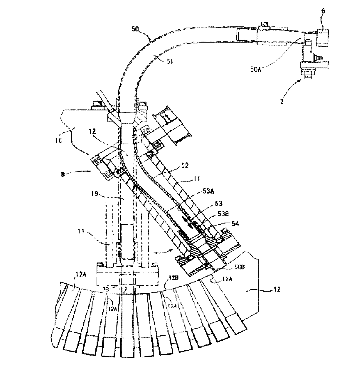
[0026] see Figure 5 , the component high-speed distributing device of the present invention comprises: servo motor one 1, servo motor two 8, wherein said servo motor one 1 connects bearing seat one 10 through connection block one 3, controls bearing seat one 10 movement; Servo motor two 8 is connected to bearing seat 2 20 through connecting block 2 9 to control the movement of bearing seat 2 20; servo motor 1 and servo motor 2 8 are both installed on the base 21, and both are vertically distributed, and servo motor 1 and servo motor The plane formed by the axis of the second 8 is parallel to the horizontal plane; the first bearing housing 10 and the second bearing housing 20 are provided with a crossed roller bearing 12 and a crossed roller bearing 2 18, and the inner rings of the two crossed roller bearings are respectively Swing arm 1 17 and swing arm 2 13 are installed, and swing arm 1 17 and swing arm 2 13 are connected through a deep groove ball bearing 30 to form a coup...


PUM


Abstract

The invention relates to a high-speed component distributing device, which comprises an installation base, a servo motor I and a servo motor II, wherein the servo motor I is connected with a bearing base I through a connecting block I and is used for controlling the bearing I base to move; the servo motor II is connected with a bearing base II through a connecting block II and is used for controlling the bearing base II to move; the servo motor I and the servo motor II are arranged on the base, and are vertically distributed; a plane constructed by the axes of the servo motor I and the servo motor II is parallel to the horizontal plane; and an intersectional roller bearing I and an intersectional roller bearing II are arranged inside the bearing base I and the bearing base II. The distributing device has the advantages of reducing the load inertia of a motor, increasing the distributing speed, eliminating high-speed vibration of a cable, reducing the occupied space, and lowering the cost simultaneously.

Description

technical field [0001] The invention relates to a material distribution of electronic components, and further relates to a material distribution device of a chip light-emitting diode (SMDLED). Background technique [0002] Due to the technological problems in the production process of SMD LEDs, products with different wavelengths and light intensities will be mixed together. Before leaving the factory, they must be tested and classified. This can be achieved through manual testing and sorting or automated testing and sorting equipment. . As the size of SMD LEDs becomes smaller and smaller (such as 0603 components), and with the gradual increase in productivity requirements, the speed requirements for automated testing and sorting equipment are getting higher and higher. One of the speed bottlenecks of automated testing and sorting equipment is the dosing device. The purpose of the dispensing device is to distribute those SMD LEDs that have been identified after the test to...

Claims


Application Information

Patent Timeline
Patent Type & Authority Patents(China)
IPC IPC(8): B07C5/36
Inventor 林琳缪来虎卓维煌李靖鹏王晨
Owner SHENZHEN HI TEST SEMICON EQUIP
Why Eureka
Try Eureka