A compound excitation synchronous starting system and method for a synchronous motor
An excitation system and synchronous start technology, applied in the direction of starting devices, etc., can solve the problems of synchronous brushless electric excitation motor start-up difficulty, synchronous brushless electric excitation generator start-up difficulty, etc., to achieve simplified towing test equipment, large excitation Current adjustment range, output power smooth and continuous effect
- Summary
- Abstract
- Description
- Claims
- Application Information
AI Technical Summary
Problems solved by technology
Method used
Image
Examples
Embodiment 1
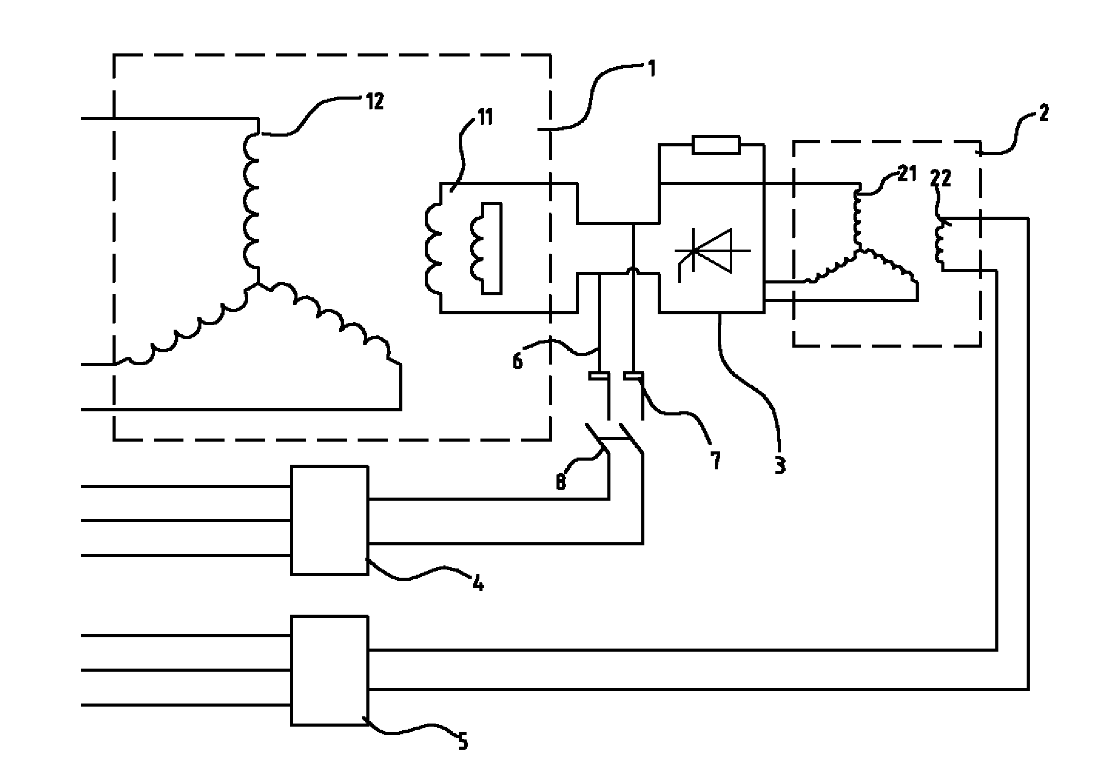
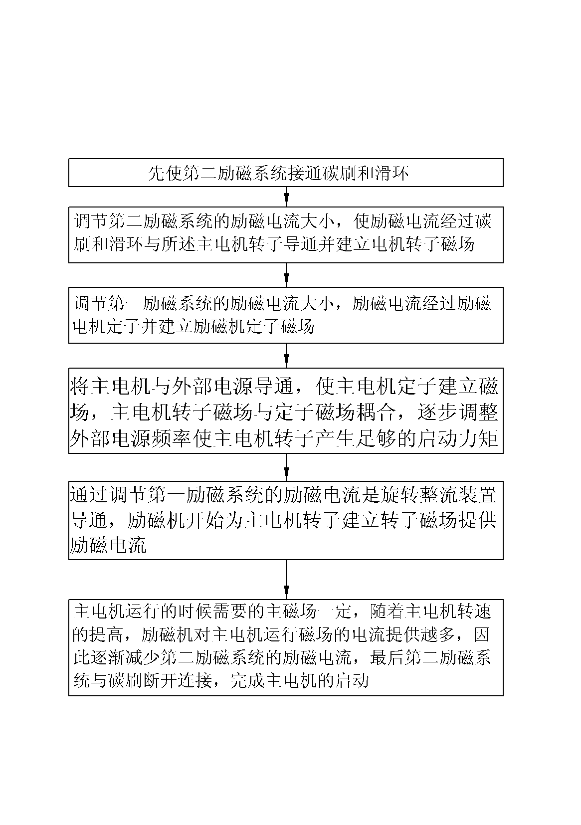
[0035] A synchronous start-up system for compound excitation of a synchronous motor, comprising a main motor 1, an exciter 2, a rotating rectifier 3, a first excitation system 5 and a second excitation system 4; the main motor rotor 11, the exciter rotor 21 and the rotating rectifier Disk 3 is synchronized. In this embodiment, the first excitation system 5 and the second excitation system 4 are excitation cabinets, which are convenient for transportation and deployment. The rotating rectifier disc 3 controls the conduction angle of the diode by a thyristor, thereby changing the overcurrent capability of the diode; the first excitation system 5 provides excitation current to the stator of the exciter 2; the rotor of the exciter 2 passes through The rotating rectifying disc 3 provides excitation current to the rotor of the main motor 1 . A synchronous slip ring 6 is provided between the rotating rectifier disc 3 and the rotor of the main motor 1, and the slip ring 6 rotates wit...
Embodiment 2
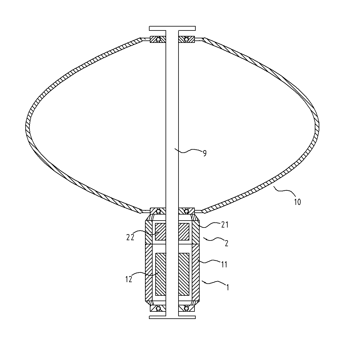
[0046] Such as figure 1 , 3 As shown, a vertical axis wind power generator includes a tower column 9, a wind wheel 10 located on the tower column 9, a main motor 1 and an exciter 2, the main motor 1 and the exciter 2 are external rotor structures, and the main motor The stator 12 and the exciter stator 22 hug the tower 9 tightly, and the wind wheel 10 , the rotor 11 of the main motor and the rotor 21 of the exciter are connected into one body and can rotate around the tower 9 synchronously. A rotating rectifying device is provided between the main motor 1 and the exciter 2. This embodiment is a rotating rectifying disc 3. The rotating rectifying device controls the conduction angle of the diode by a silicon controlled rectifier, thereby changing the overcurrent capability of the diode. The rotating rectifying device and the Main motor, rotor 11 and exciter rotor 21 are synchronized. The exciter 2 is controlled by a first excitation system 5 which supplies an excitation curre...
PUM
 Abstract
Description
Claims
Application Information
 - R&D
- Intellectual Property
- Life Sciences
- Materials
- Tech Scout
- Unparalleled Data Quality
- Higher Quality Content
- 60% Fewer Hallucinations
Browse by: Latest US Patents, China's latest patents, Technical Efficacy Thesaurus, Application Domain, Technology Topic, Popular Technical Reports.
© 2025 PatSnap. All rights reserved.Legal|Privacy policy|Modern Slavery Act Transparency Statement|Sitemap|About US| Contact US: help@patsnap.com


