Power supply ageing system and load balance control method
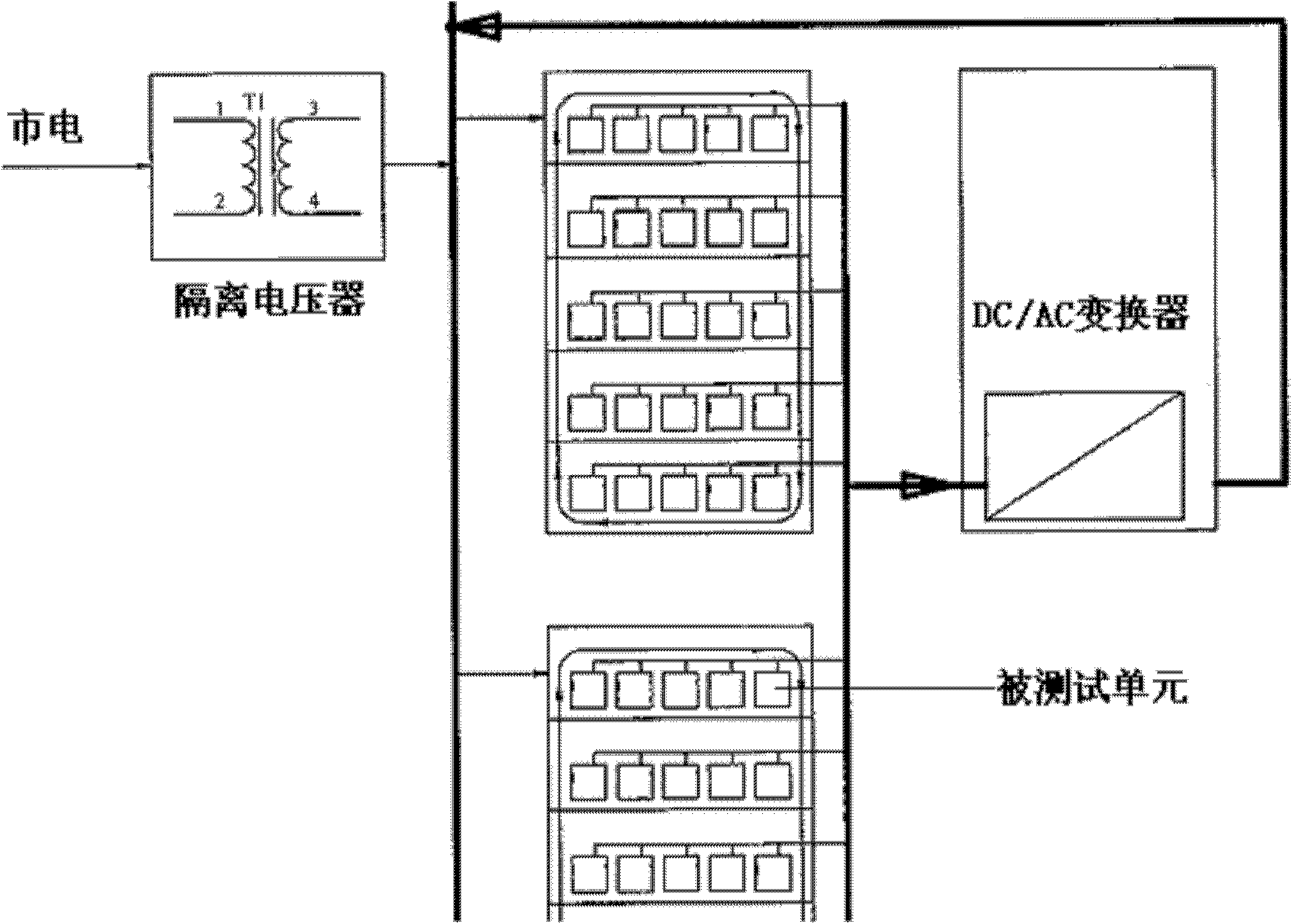
A power aging and system balancing technology, applied in the field of power electronics, can solve problems such as low feedback efficiency, fixed loading power, and increased costs, and achieve the effects of improving efficiency, reducing costs, and reducing energy consumption
- Summary
- Abstract
- Description
- Claims
- Application Information
AI Technical Summary
Problems solved by technology
Method used
Image
Examples
Embodiment 1
[0032] An embodiment of the present invention provides a power aging system, such as figure 2 As shown, the power aging system includes: a system balance supply unit 201, a regenerative load unit 202 and a DC conversion AC unit 203; wherein,
[0033] The system balance supply unit 201 is connected to the mains and output to the high-voltage DC bus, which is used to generate the DC power required for the constant current balance of the power aging system; the system balance supply unit 201 outputs a fixed voltage, and the power supply is aged by increasing or decreasing the output current The system maintains a constant current balance;
[0034] The regenerative load unit 202 is connected to the unit under test 200, and is connected in parallel with the system balance supply unit 201, and is boosted and output to the high-voltage DC bus for converting the low-voltage direct current output by the unit under test 200 into a high-voltage direct current; the regenerative load unit...
Embodiment 2
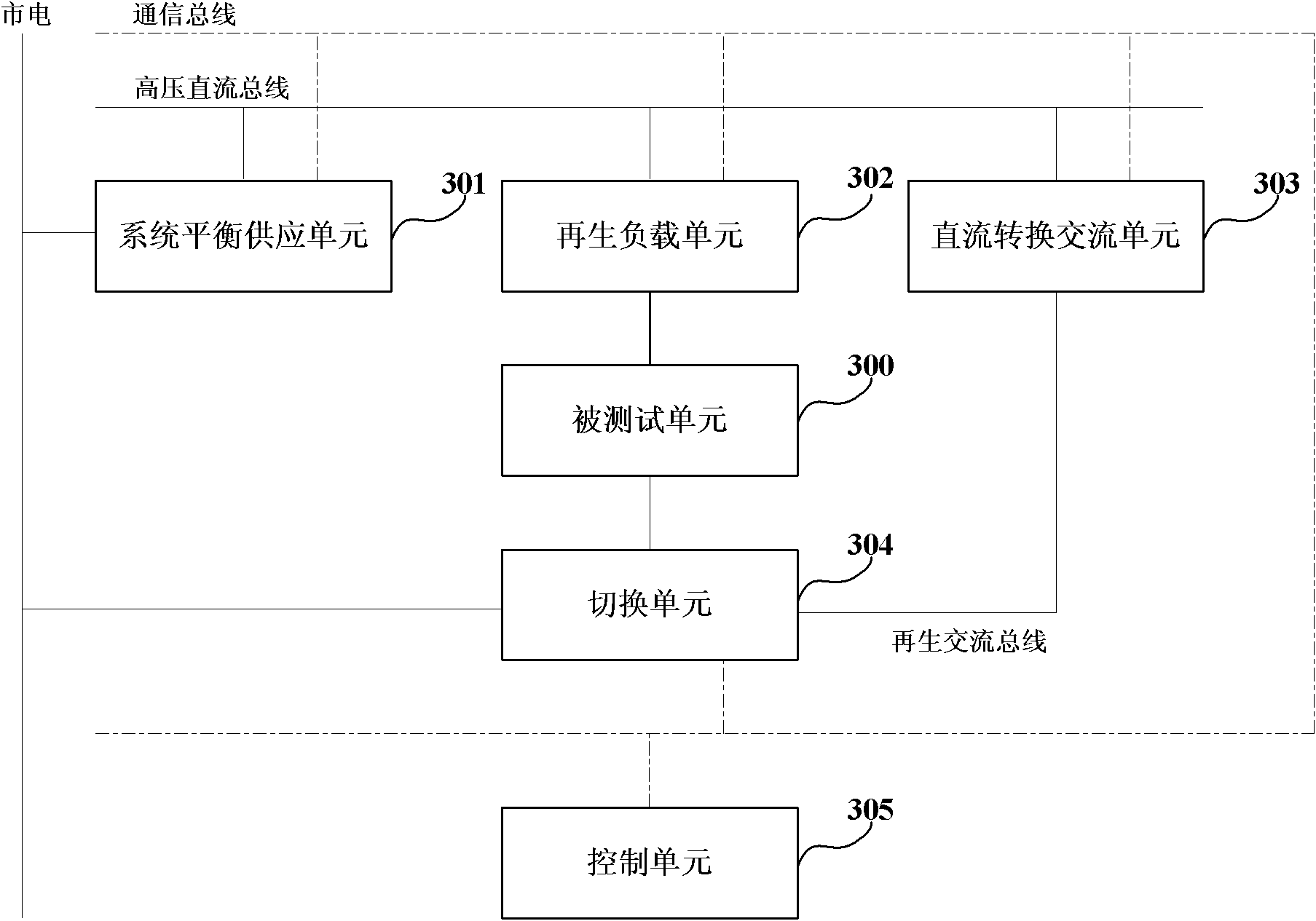
[0045] An embodiment of the present invention provides a power aging system, such as image 3 As shown, the power aging system includes: a system balance supply unit 301, a regenerative load unit 302, and a DC conversion AC unit 303; as described in Embodiment 1, details will not be repeated here.
[0046] Such as image 3 As shown, the power aging system may further include: a switching unit 304;
[0047] One end of the switching unit 304 is connected to the unit under test 300 , and the other end is connected to the mains or the regenerative AC bus for switching through the switch so that the mains or the regenerative AC bus provides the required AC power for the unit under test 300 .
[0048] Therefore, the switching unit 304 can connect the input end of the unit under test to the shared energy source (System Share Power) of the utility power generation system, or, be connected to the regenerative energy source fed back by the regenerative AC bus; therefore, the power cons...
Embodiment 3
[0082] The power aging system of this embodiment is basically as described in Embodiment 2, and will not be repeated here. The main difference from Embodiment 2 is that, except that the function of sampling analog signals such as current and voltage and converting them to AC / DC is implemented by hardware, other functions of the control unit are realized by software function modules, and the host computer Run each software function module to realize the online control of the system balance supply unit, regenerative load unit, DC conversion AC unit and switching unit; it is also possible to modify and set the system through the man-machine dialogue window of the host computer according to different tested units Each control parameter of the balance supply unit, the regenerative load unit, the DC conversion AC unit, the balance determination unit and the signal sending unit. Therefore, the operation of the system is more intuitive, the adaptability is stronger, and it can be appl...
PUM
 Abstract
Description
Claims
Application Information
 - R&D
- Intellectual Property
- Life Sciences
- Materials
- Tech Scout
- Unparalleled Data Quality
- Higher Quality Content
- 60% Fewer Hallucinations
Browse by: Latest US Patents, China's latest patents, Technical Efficacy Thesaurus, Application Domain, Technology Topic, Popular Technical Reports.
© 2025 PatSnap. All rights reserved.Legal|Privacy policy|Modern Slavery Act Transparency Statement|Sitemap|About US| Contact US: help@patsnap.com


