
Waterproof position limit switch

A travel switch and switch group technology, applied in electrical switches, electrical components, circuits, etc., can solve the problems of affecting the safe operation of the system, easy damage to the switch, and jamming of the switch, and achieve a compact structure, easy assembly and adjustment, and intuitive structure. Effect

Active Publication Date: 2013-08-28
G & A TECH
View PDF4 Cites 0 Cited by
  • Summary
  • Abstract
  • Description
  • Claims
  • Application Information

AI Technical Summary

Problems solved by technology

However, although the existing waterproof limit switch can meet the waterproof requirements, it is difficult to adapt to long-term operation in a high-temperature environment as high as 400 ° C. If there is high random vibration at the same time, it is difficult to withstand. Not only the switch is easy to be damaged, but also the switch is jammed or Stuck faults affect the safe operation of the system

Method used


Image

  • Waterproof position limit switch
  • Waterproof position limit switch
  • Waterproof position limit switch

Examples


Embodiment Construction

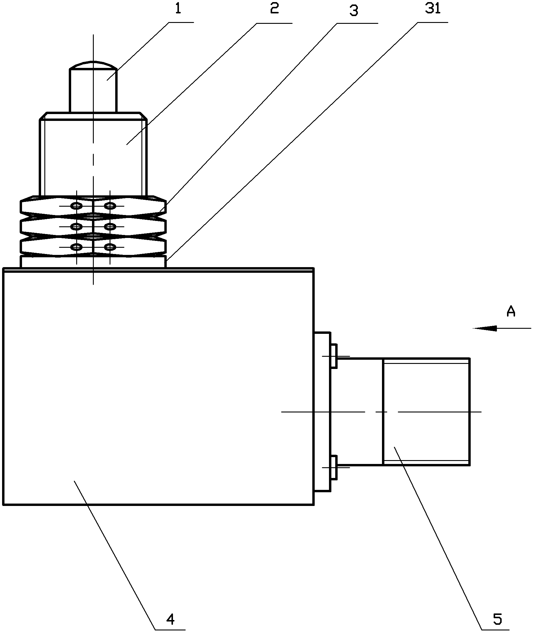
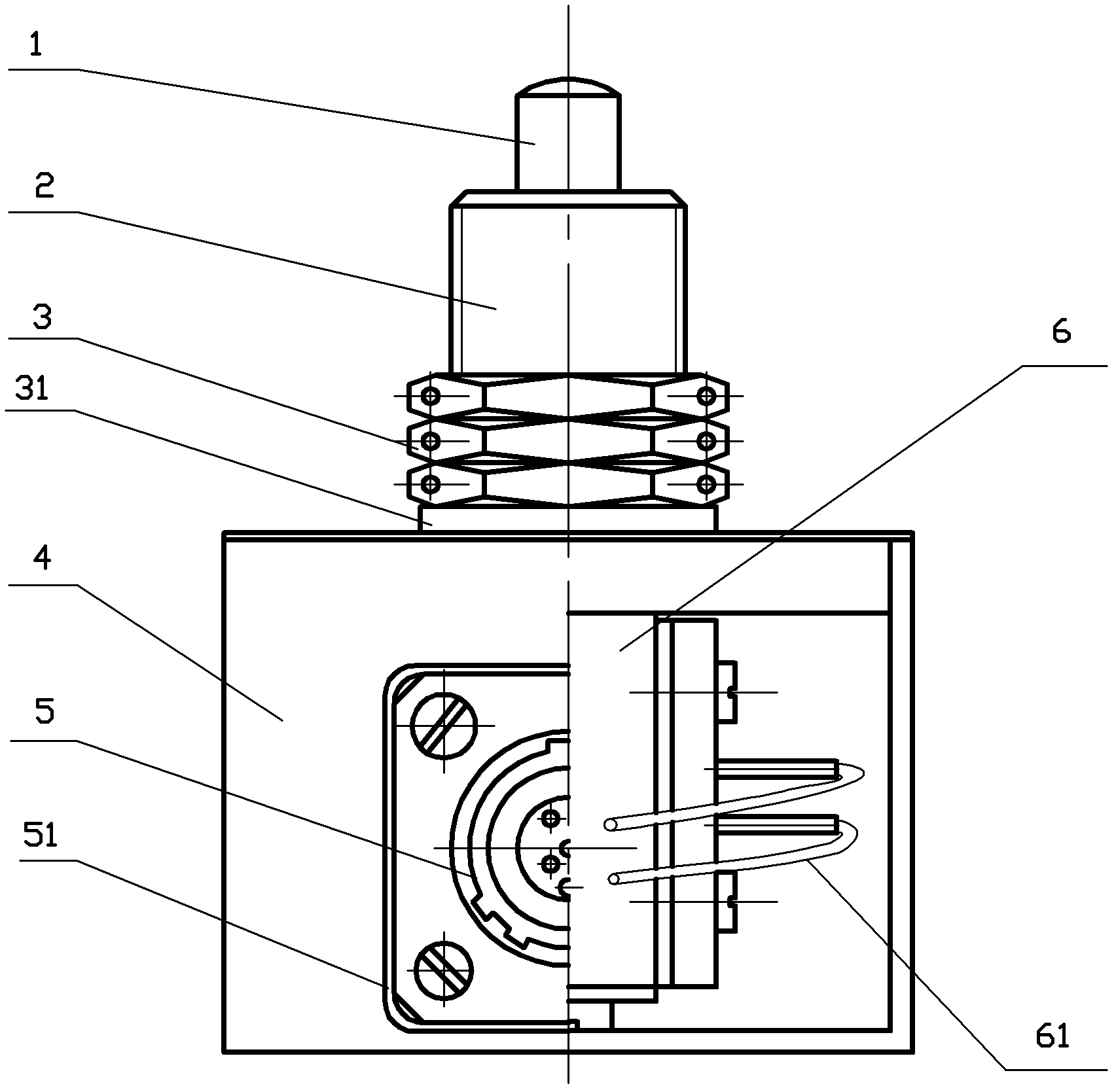
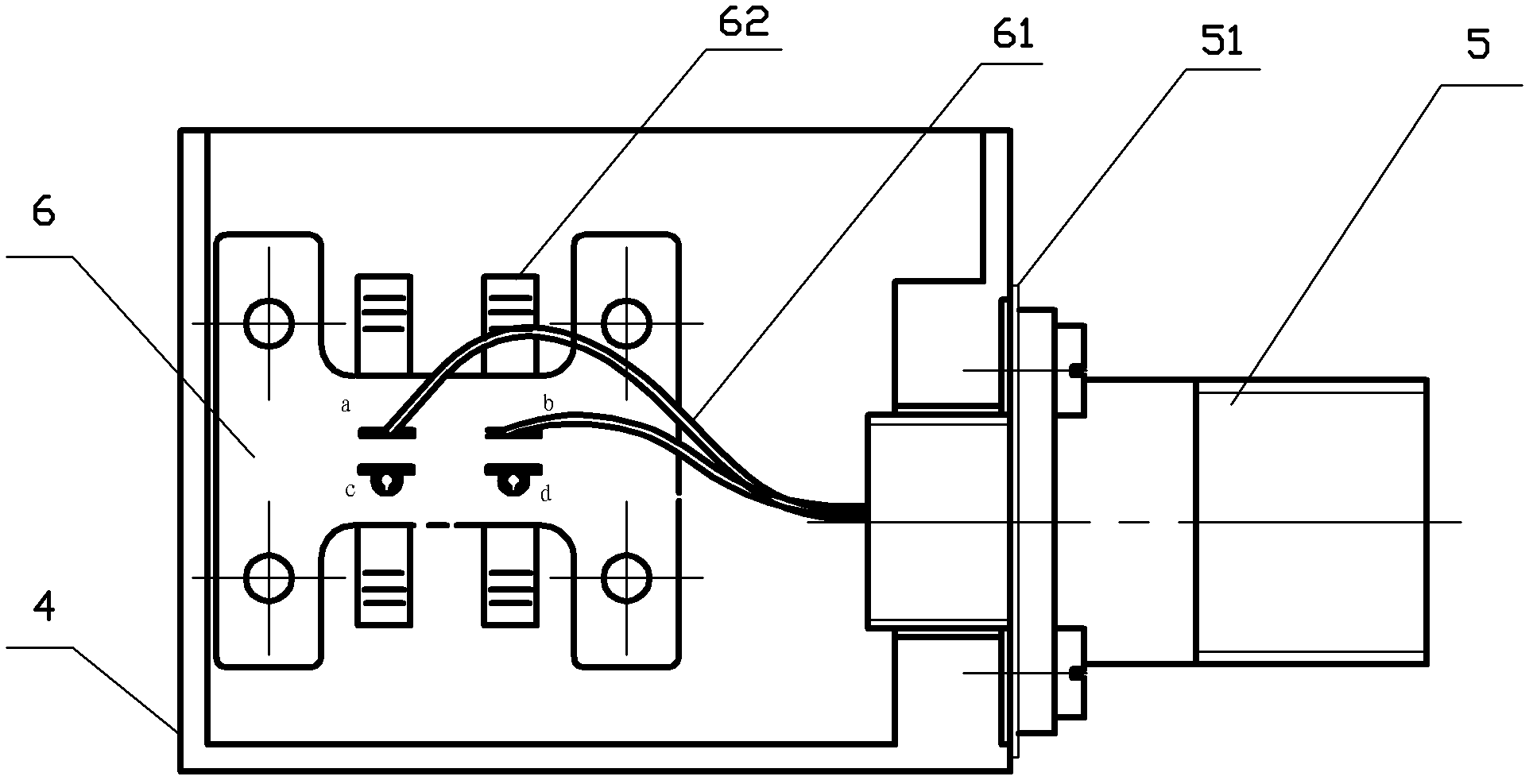
[0023] The overall structure of the waterproof travel switch is as follows: figure 1 , 2 The shown includes a base group and a switch group matched with it. The base group includes a base 4 and a socket 5 with a circuit output interface. The switch group includes a shell 2, a combination button 1, a contact spring group 6 and a compression spring 14. This The base 4 in the scheme is a cuboid, the bottom surface is sealed and connected to the side surface, the side surface has a mounting hole to connect the socket 5, and the top surface is a rectangular opening. Such as Figure 5 As shown, the shell 2 of the switch group includes a button shell 21, a cover plate 22 and a mounting frame 23. The cover plate 22 matches the rectangular opening on the top surface of the base, and the button shell 21 is vertically sealed and connected to the top of the button hole of the cover plate 22. The frame 23 is fixed vertically under the cover plate 22 .

[0024] The inner hole of the butt...


PUM


Abstract

The invention provides a waterproof position limit switch. The side surface of a base is connected with a socket and each surface is sealed; a cover plate of a switching group shell seals an opening at the top surface of the base; a button shell is connected with the upper part of the button hole of the cover plate, and mounting brackets are fixedly connected with the lower part of the cover plate; an electric conductor is embedded in an insulated cylinder of a combined button and the insulated cylinder of the combined button is arranged between two contact spring groups of the mounting brackets; a button at the top end stretches out the top hole of the button shell and a bottom end abuts against a compressed spring; each contact spring group has a pair of upper contact springs and a pairof lower contact springs; the combined button is connected with the upper contact springs normally and the button is pressed down to switch on the lower contact springs; high-temperature seal rings or gaskets are arranged between the combined button and the button shell and between the socket and the base; the base and the cover plate are welded, and the button shell is in threaded connection with the cover plate and fastened with a nut, thus ensuring the overall sealing and waterproofness of the switch; and the upper and lower edges of a cuboid at the lower part of the combined part are provided with grooves which are matched with the contact springs so as to smoothly slide the electric conductor. The switch adapts to the high-temperature and high random vibration environment and is goodin waterproofness, high in reliability, compact in structure and simple and convenient to assemble and debug.

Description

(1) Technical field [0001] The invention relates to a travel switch of an electrical device, in particular to a waterproof travel switch adaptable to a 400-degree high temperature and high random vibration environment. (2) Background technology [0002] The travel switch is also called a position switch or a limit switch. Its function is to convert the mechanical displacement into an electrical signal to change the operating state of the motor, that is, to automatically stop, reverse, change speed or cycle according to a certain stroke, so as to control the mechanical movement or realize safety protection. Different types of limit switches are widely used in automatic control systems in various industries. [0003] In order to meet the requirements of different occasions, various series of limit switches have been developed. There are many types of waterproof limit switches, and their shells are sealed to be suitable for use under overall immersion and rain conditions. How...

Claims


Application Information

Patent Timeline
Patent Type & Authority Patents(China)
IPC IPC(8): H01H9/04H01H3/16
Inventor 郑郑陈兴
Owner G & A TECH
Learn More