
Supporting device for lens in lithography projection objective lens

A supporting device and lithographic projection technology, which is applied in the direction of photolithography exposure device, microlithography exposure equipment, installation, etc., can solve the problems of reducing the surface shape accuracy of the lens, and achieve reliable positioning, support isolation, and easy processing and manufacturing. Effect

Inactive Publication Date: 2011-12-14
CHANGCHUN INST OF OPTICS FINE MECHANICS & PHYSICS CHINESE ACAD OF SCI
View PDF5 Cites 27 Cited by
  • Summary
  • Abstract
  • Description
  • Claims
  • Application Information

AI Technical Summary

Problems solved by technology

[0004] In order to solve the problem that the support of the optical lens in the processing and manufacturing process of the existing lithography projection objective lens is affected by the adjustment force and the processing error, the surface shape accuracy of the lens is reduced, and a support for the lens in the lithography projection objective lens is provided. device

Method used


Image

  • Supporting device for lens in lithography projection objective lens
  • Supporting device for lens in lithography projection objective lens
  • Supporting device for lens in lithography projection objective lens

Examples


specific Embodiment approach 1

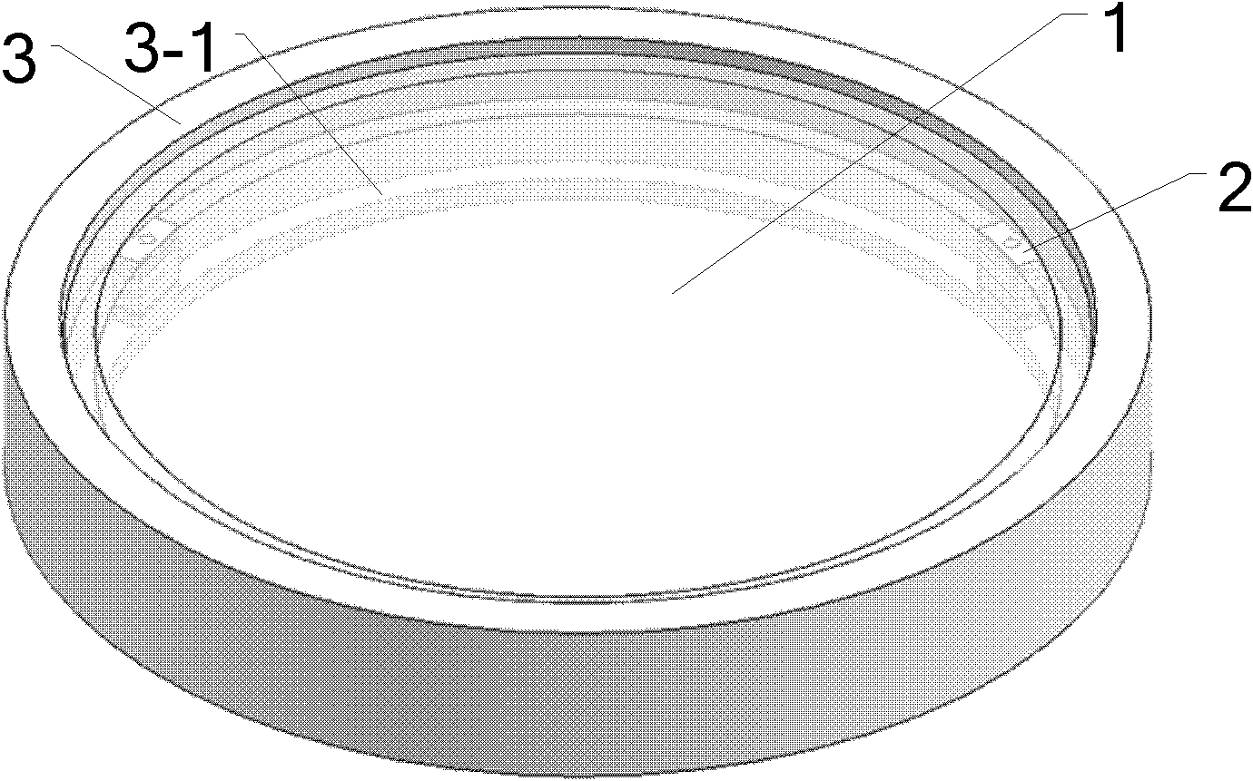
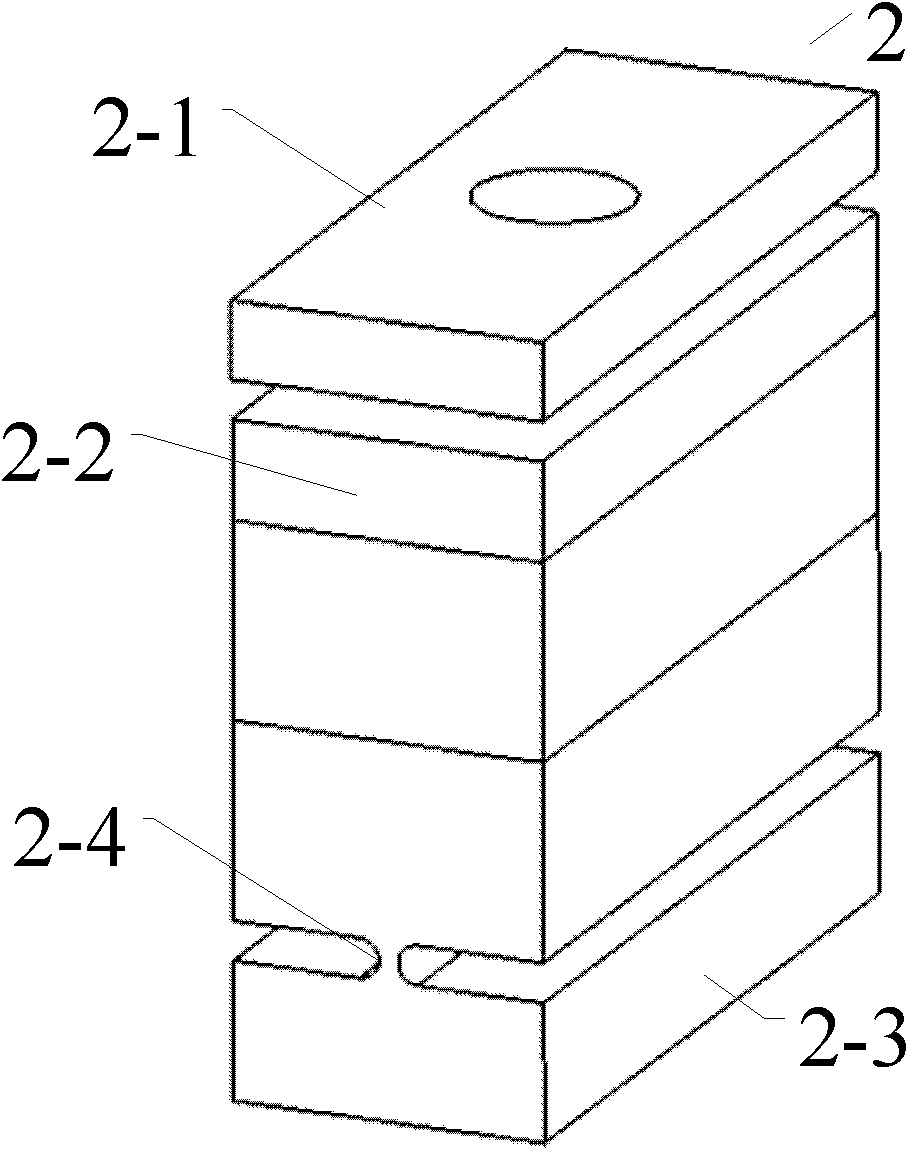
[0013] Specific implementation mode 1. Combination Figure 1 to Figure 4 Describe this embodiment, a kind of supporting device of eyeglass in lithographic projection objective lens, this device comprises support 2 and picture frame 3, lens 1 is supported in picture frame 3 by support 2, and described picture frame 3 is ring-shaped, in ring picture frame 3 A supporting part 3-1 is provided at the place where the bottom extends inwardly of the ring.

[0014] The lens 1 described in this embodiment is processed with a ring of flange flange 1-1 on the edge portion outside its clear aperture, and the upper and lower surfaces of the flange flange 1-1 are both flat, which is beneficial to the lens 1. Support positioning on support 2. The material of the lens 1 is fused silica or calcium fluoride commonly used in deep ultraviolet projection lithography objective lenses, and may also be common optical materials used in ordinary lenses. The lens 1 is fixed on the bearing block 2-1 of ...


PUM


Abstract

The invention discloses a supporting device of a lens in a photoetching projection objective, and relates to the technical field of manufacturing and debugging of lenses of deep ultraviolet photoetching machine projection objectives. The supporting device provided by the invention can be used for solving the problem that the surface figure accuracy of the lens is reduced because the supporting ofan optical lens is influenced by debugging force and mismachining tolerance during the processing and manufacturing of the existing photoetching projection objective. The supporting device comprises a supporting seat and a lens frame, wherein the lens is supported in the lens frame by virtue of the supporting seat; the lens frame is annular, and a supporting part is arranged at a position, which extends towards the interior of a ring, at the bottom of the annular lens frame. The supporting device is simple in structure and easy to process and manufacture, can perform ultra-precise positioningon an optical element, can effectively compensate changes of external environment so as to favorably maintain the surface figure accuracy of the optical element, and can ensure that the projection objective obtains excellent imaging performance. The supporting device is applicable to a refraction type optical lens, and can also be used for high-accuracy supporting of a reflection type optical element.

Description

technical field [0001] The invention relates to the technical field of manufacturing and assembling a projection objective lens of a deep ultraviolet lithography machine, in particular to a frame structure that can be used for high-precision support of a lithography projection objective lens. Background technique [0002] The processing and manufacturing of lithography projection objective lens is a very precise and complex process. As the requirements for chip line width fineness become higher and higher, the NA value of the optical system of the lithography machine is also increasing. The caliber of the optical elements in the lithography projection objective lens is also increasing, and the clear aperture of the lens is often between 80-320mm. In order to achieve high-quality imaging performance and obtain higher resolution, it is required that the optical components should maintain the RMS value of surface shape accuracy in the range of several nanometers while obtainin...

Claims


Application Information

Patent Timeline
Patent Type & Authority Applications(China)
IPC IPC(8): G02B7/02G03F7/20
Inventor 倪明阳巩岩张巍赵磊王学亮袁文全
Owner CHANGCHUN INST OF OPTICS FINE MECHANICS & PHYSICS CHINESE ACAD OF SCI
Learn More