SMT method and structure for radiographic detection of pipe welds

A technology of radiographic detection and patching, which is applied in the fields of patching of tube welds, patching structures of radiographic testing, and patching structures of tube welding seams. , Inconvenient positioning and other problems, to achieve the effect of waste utilization, process reduction and convenient operation

Inactive Publication Date: 2011-12-14
CHINA 19TH METALLURGICAL CORP
View PDF2 Cites 18 Cited by
  • Summary
  • Abstract
  • Description
  • Claims
  • Application Information

AI Technical Summary

Problems solved by technology

[0005] The disadvantages of the above method are: 1. When using a tape measure to locate the clock, because the tape measure is elastic and extensible, it is not convenient to locate on the circular weld; 2. When fixing the film with a magnet, consider reducing the backscattering effect. Therefore, try to fix the magnets on the 4 corners of the film as much as possible. Doing so can not guarantee the tightness of the whole film and affects the quality of the film; Power consumption, low efficiency

Method used


Image

  • SMT method and structure for radiographic detection of pipe welds
  • SMT method and structure for radiographic detection of pipe welds
  • SMT method and structure for radiographic detection of pipe welds

Examples


Embodiment

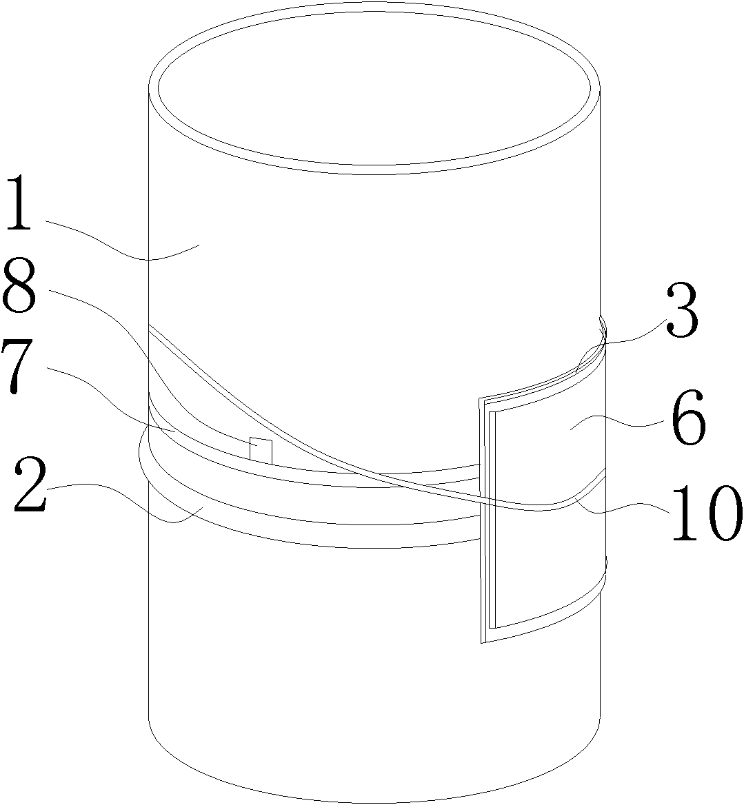
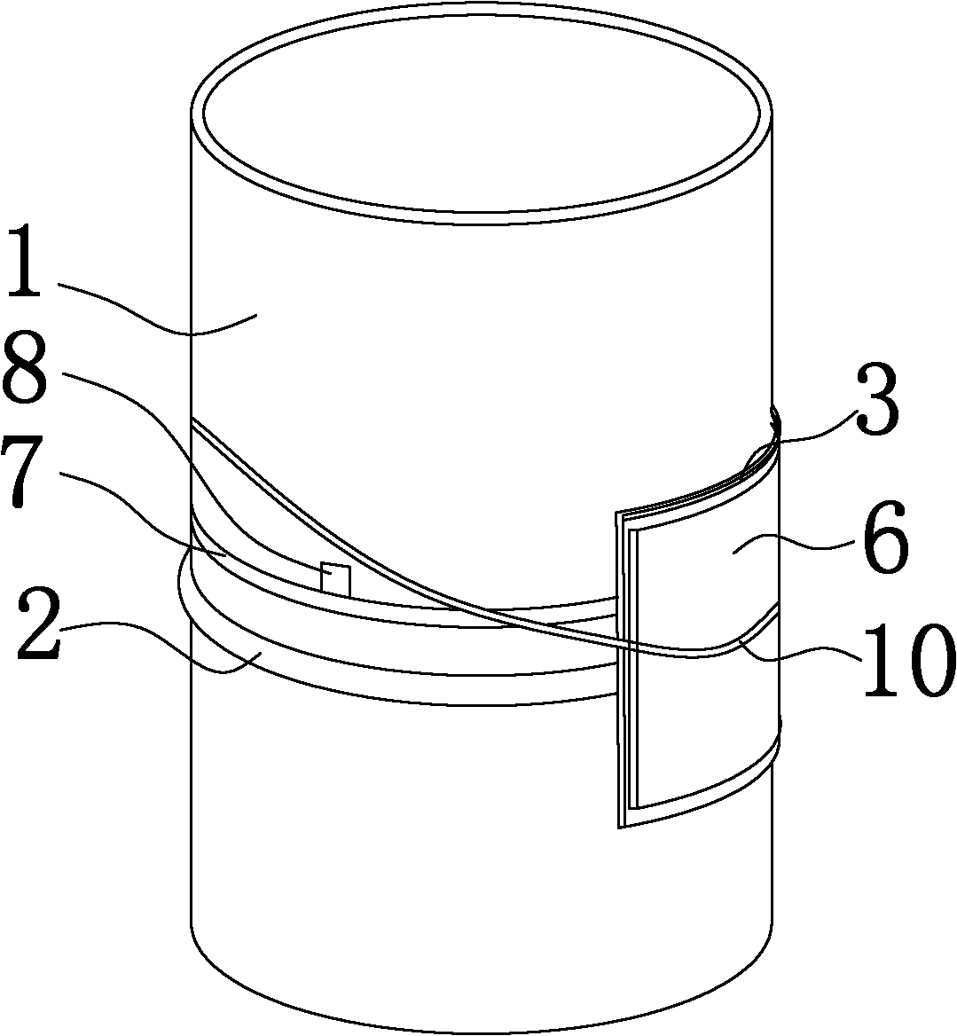
[0037] Taking a pipe butt joint with a diameter of 159mm as an example, if 4 times of transillumination are performed, the effective length of each transmission is about 125mm. Use the following steps to patch:

[0038] A. Make segmented tape 7, put the medical tape on the platform, with the adhesive side facing up, put the lead characters of the numbers 1, 2, 3 and 4 facing up, stick them on the tape at intervals of 125mm, pay attention to the lead characters Need to be exposed to the tape. After the lead type is glued, fold the adhesive tape in half from the end of the No. 4 lead type to the direction of the No. 1 lead type, and make the upper adhesive tape longer than the lower adhesive tape, that is, make the adhesive side of the upper adhesive cloth face downward to expose a section, so as to surround the segmented tape 7 Carry out adhesion when checking steel pipe 1, so just made a subsection band 7.

[0039] B. Fix the segmented tape 7 to the side of the transillumina...


PUM


Abstract

The invention discloses a patch method for radiographic detection, in particular to a patch method for radiographic detection of pipe welds. The present invention provides a patch method for segmentally accurate tube weld radiographic detection, comprising the following steps: A, making segmented bands, using the marking on the segmented bands to mark the segmented bands as n sections, where n is the transmission The number of times, the length of each section is L / n, and L is the outer circumference of the steel pipe to be inspected; B. Set the produced segmented belt around the outer circumference of the steel pipe to be inspected, and the segmented belt is arranged next to the weld; C. , Place the penetrometer and various marks on the side of the pipe wall, attach the dark bag box to the weld and cover the section to be inspected, the penetrometer and various marks, so that the inside of the dark bag box The length direction of the film is consistent with the circumferential direction of the welding seam, and the backscattering lead plate is attached to the dark bag box. Segments are marked with segmented bands and markers, so the images generated during multiple transilluminations are more accurately correlated, improving efficiency and improving the quality and accuracy of negatives.

Description

technical field [0001] The invention relates to a patch method for radiographic detection, in particular to a patch method for radiographic detection of pipe welds. In addition, the present invention also relates to a patch structure for radiographic detection, especially a patch structure for radiographic detection of pipe welds. Background technique [0002] In the metal non-destructive testing radiographic flaw detection process, it is a necessary process to attach the intensifying screen, the marking lead, the penetrometer, and the film to the pipe wall, so that the ray passes through the weld after being emitted from the source, and produces potential damage on the film. Finally, through developing, fixing and other processes, the image is clearly displayed, which is convenient for naked eye observation. [0003] After calculating the transillumination parameters, before the transillumination, the conventional method of patching is: 1. Use the clock positioning method,...

Claims


Application Information

Patent Timeline
IPC IPC(8): G01N23/04
Inventor 蔡仲斌李昕蕊黄成楷卢廷荣肖波李钢罗永忻
Owner CHINA 19TH METALLURGICAL CORP
Why Eureka
Try Eureka